This thread has been locked.

If you have a related question, please click the "Ask a related question" button in the top right corner. The newly created question will be automatically linked to this question.

MSP430F6736A: ADC10 DMA Interrupt is lost

Part Number: MSP430F6736A

Hi TI Team,

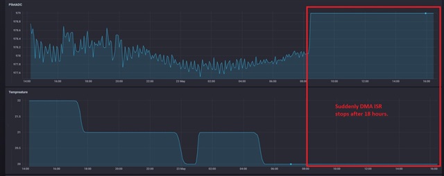
I am using DMA to fetch the conversion result from ADC10 module. It has been observed that sometimes DMA interrupts gets lost or maybe ADC10 module gets stuck. Please check the attached snapshot and below code Initialization.

void initAdc10(void) {
// Setup P1.2 A0, 1.1 A1, 1.0 A2
P1SEL |= BIT0 | BIT1 | BIT2; // Set P1.0,.1,.2 to non-IO
__disable_interrupt(); // Disable interrupts; Port Map cnfg
PMAPKEYID = PMAPKEY; // Enable access Port Mapping regs
P1MAP2 = PM_ANALOG; // Enable A0
P1MAP1 = PM_ANALOG; // Enable A1
P1MAP0 = PM_ANALOG; // Enable A2
PMAPKEYID = 0; // Disable access Port Mapping regs
__enable_interrupt(); // Re-enable all interrupts

// Setup ADC10
ADC10CTL0 = ADC10SHT_2 | ADC10MSC | ADC10ON; // 16ADCclks, MSC, ADC ON
ADC10CTL1 = ADC10SHP | ADC10CONSEQ_3; // pulse sample mode, repeated sequence
ADC10CTL2 = ADC10RES; // 10-bit resolution
ADC10MCTL0 = ADC10INCH_2; // A0,A1,A2(EoS), AVCC reference

// Setup DMA0 (ADC10IFG trigger)
DMACTL0 = DMA0TSEL_24; // ADC10IFG trigger
DMA0SZ = 192;
__data20_write_long((uintptr_t) &DMA0SA, (uintptr_t) &ADC10MEM0);
// Source single address
__data20_write_long((uintptr_t) &DMA0DA, (uintptr_t) &ADC_Result[0]);
// Destination array address
DMA0CTL = DMADT_4 | DMADSTINCR_3 | DMASWDW | DMAEN | DMAIE;
}

#if defined(__TI_COMPILER_VERSION__) || defined(__IAR_SYSTEMS_ICC__)
#pragma vector=DMA_VECTOR
__interrupt void DMA0_ISR(void)
#elif defined(__GNUC__)
void __attribute__ ((interrupt(DMA_VECTOR))) DMA0_ISR (void)
#else
#error Compiler not supported!
#endif
{
switch (__even_in_range(DMAIV, 16))
{
case DMAIV_NONE: break; // No interrupts
case DMAIV_DMA0IFG: // DMA0IFG = DMA Channel 0
ADC10CTL0 &= ~ADC10ENC; // 64 conversions complete
dma_flag = 1;
break;
case DMAIV_DMA1IFG: break; // DMA1IFG = DMA Channel 1
case DMAIV_DMA2IFG: break; // DMA2IFG = DMA Channel 2
case 8: break; // Reserved
case 10: break; // Reserved
case 12: break; // Reserved
case 14: break; // Reserved
case 16: break; // Reserved
default: break;
}
}

// ADC main task

void adc_main(void) {

if (dma_flag) {

ADC10CTL0 |= ADC10ENC | ADC10SC;

dma_flag = 0;

}

}

  • Yes, I have already checked the Errata sheet but I don't think DMA7 is the case here even TI has provided the same example of DMA. Please check the below TI example - 

    unsigned int ADC_Result[64];

    int main(void)
    {
    unsigned char i;
    volatile unsigned int ADC_Result_Sum;
    volatile unsigned int ADC_Result_Average;

    WDTCTL = WDTPW | WDTHOLD; // Stop WDT

    // Setup P1.1 A1, P1.0 output
    P1SEL |= BIT1; // Set P1.1 to non-IO
    __disable_interrupt(); // Disable interrupts; Port Map cnfg
    PMAPKEYID = PMAPKEY; // Enable access Port Mapping regs
    P1MAP1 = PM_ANALOG; // Enable A1
    PMAPKEYID = 0; // Disable access Port Mapping regs
    __enable_interrupt(); // Re-enable all interrupts
    P1DIR |= BIT0; // Set P1.0 to output direction
    P1OUT &= ~BIT0; // Clear P1.0

    // Configure ADC10 - pulse sample mode; software trigger;
    ADC10CTL0 = ADC10SHT_2 | ADC10ON | ADC10MSC; // 16ADCclks, ADC on
    ADC10CTL1 = ADC10SHP | ADC10CONSEQ_2; // pulse sample mode, rpt single ch
    ADC10CTL2 = ADC10RES; // 10-bits of resolution
    ADC10MCTL0 = ADC10INCH_1; // A1, AVCC ref

    // Configure DMA (ADC10IFG trigger)
    DMACTL0 = DMA0TSEL_24; // ADC10IFG trigger
    DMA0SZ = 64; // 64 conversions
    __data20_write_long((uintptr_t) &DMA0SA, (uintptr_t) &ADC10MEM0);
    // Source single address
    __data20_write_long((uintptr_t) &DMA0DA, (uintptr_t) &ADC_Result[0]);
    // Destination array address
    DMA0CTL = DMADT_4 | DMADSTINCR_3 | DMAEN | DMAIE;
    // Repeated single transfer
    // Increment destination
    // Word access
    // Enable int after 64 conversions
    while (1)
    {
    ADC10CTL0 |= ADC10ENC | ADC10SC; // Sampling and conversion start

    __bis_SR_register(LPM0_bits | GIE); // Enter LMP0 w/ interrupt
    __no_operation(); // For debug only

    ADC_Result_Sum = 0x0; // clear accumulate register
    for (i = 0; i < 64; i++) // BREAKPOINT HERE; View ADC_Result
    {
    ADC_Result_Sum += ADC_Result[i];
    }
    ADC_Result_Average = ADC_Result_Sum >> 6; // Average of 64 conversions results

    __delay_cycles(50000); // delay before next 64 conversions
    }
    }

    #if defined(__TI_COMPILER_VERSION__) || defined(__IAR_SYSTEMS_ICC__)
    #pragma vector=DMA_VECTOR
    __interrupt void DMA0_ISR(void)
    #elif defined(__GNUC__)
    void __attribute__ ((interrupt(DMA_VECTOR))) DMA0_ISR (void)
    #else
    #error Compiler not supported!
    #endif
    {
    switch (__even_in_range(DMAIV, 16))
    {
    case DMAIV_NONE: break; // No interrupts
    case DMAIV_DMA0IFG: // DMA0IFG = DMA Channel 0
    ADC10CTL0 &= ~ADC10ENC; // 64 conversions complete
    __bic_SR_register_on_exit(LPM0_bits); // Exit LPM0 on return
    break;
    case DMAIV_DMA1IFG: break; // DMA1IFG = DMA Channel 1
    case DMAIV_DMA2IFG: break; // DMA2IFG = DMA Channel 2
    case 8: break; // Reserved
    case 10: break; // Reserved
    case 12: break; // Reserved
    case 14: break; // Reserved
    case 16: break; // Reserved
    default: break;
    }
    }


  • How do you tell that the DMA/ADC has stalled? Specifically: what is PilotADC telling us?

    ADC10CTL0 &= ~ADC10ENC; // 64 conversions complete

    This doesn't stop the ADC immediately -- it will keep converting until the sequence is done [Ref UG (SLAU208Q) Sec 27.2.7.6]. This sets up a race which allows the ADC to be restarted before it has stopped, which is Erratum ADC42 [Ref Errata (SLAZ646R) p. 4] The Example glosses over this possibility with its __delay_cycles and shorter sequence.

    Try inserting before setting ADC10SC:

    >  while (ADC10CTL1 & ADCBUSY) /*EMPTY*/;  // Quiesce. Shouldn't take long.

  • DMA/ADC has stalled because normally pilotADC (external sensor signal) varies 1-5 counts every second and you can check the board temperature, it got fixed too. Normally in daytime or after long time it should vary by 1 or 2 degrees. I am adding the "while (ADC10CTL1 & ADCBUSY)". I hope this will resolve the issue. 

    Thanks Gary and Bruce.

**Attention** This is a public forum