This thread has been locked.

If you have a related question, please click the "Ask a related question" button in the top right corner. The newly created question will be automatically linked to this question.

MSP430I2021: Circuit configuration of DCO and relationship between external resistance value and oscillation frequency

Part Number: MSP430I2021


Hi experts,

Please let me check about the DCO of MSP430I2021.

Q1: Could you please share the information about the equivalent circuit of DCO?
Basically, I am aware that there is no circuit information on DCOs for any MSP430 device, but any reference information would be helpful.
Example: Multi-Frequency Range and Tunable DCO on MSP432P4xx Microcontrollers (Rev. A)

Q2: Could you please share the characteristics of external resistance vs. oscillation frequency (data like a graph)?
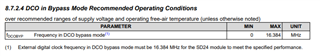
When using DCO, the datasheet states that the external resistance connected to ROSC should be 20[kΩ] with an accuracy of ±0.1[%] and 50[ppm/℃]. If you have test data of oscillation frequency with different resistance value, it would be helpful if you could share it with us.

As a side note, my customer is using MSP430I2021 for their product, and they are experiencing UART communication instability at high temperature. We have checked the register setting values of UART and other usage separately, but we are also investigating DCO.

[Postscript_20210603]

A customer has created a prototype board using MSP430I2021, but UART communication error occurs at high temperature (70°C).

Q3:If you cannot provide the characteristics of external resistance vs. oscillation frequency, could you please provide the characteristic diagram of oscillation accuracy (or clock jitter) vs. Ta?
In the data sheet, only Ta=25[°C] is described.

Q4:If the UART communication becomes unstable due to temperature, as in this case, is there no other solution but to use an external oscillator instead of an internal oscillator (DCO)?
If there are other measures, I would appreciate it if you could let me know.

Best regards,
O.H

  • Hello OH,

    Unfortunately, I don't have an equivalent circuit or a resistance vs oscillation frequency data that you requested.  The best I can provide is the DCO Overal Tolerance Table 8.7.2.3

    If the DCO is not accurate enough, it is possible to put the DCO in bypass mode and pass in your own clock source up to 16.384 MHz.  (but it must be 16.384 for the SD24)

    Finally, it is possible to output MCLK or SMCLK directly on a GPIO if they want to measure and evaluate the CPU clock frequency.  

    Thanks,

    JD

  • Hello JD,

    Thanks for the reply. I understood.

    If the DCO is not accurate enough, it is possible to put the DCO in bypass mode and pass in your own clock source up to 16.384 MHz.  (but it must be 16.384 for the SD24)

    Finally, it is possible to output MCLK or SMCLK directly on a GPIO if they want to measure and evaluate the CPU clock frequency.  

    Thanks,

    Due to the design of the board, MCLK and SMCLK could not be used, so they pseudo-checked the DCO output by toggling the available GPIO pins. As a result, when the resistance value is low, the error seems to be small, but when the resistance value is high, the error is obviously large, according to this report.

    I have asked the customer to confirm the operation when using an external oscillator, so I will share any problems with you.

    Best bregards,
    O.H

**Attention** This is a public forum