This thread has been locked.

If you have a related question, please click the "Ask a related question" button in the top right corner. The newly created question will be automatically linked to this question.

MSP430G2333: MSP430G2333IPW28R - I2C Tx

Part Number: MSP430G2333

//IAR Assembler for MSP430 7.11.1 (7.11.1.983)
#include "msp430.h"                                                             ; #define controlled include file

                 NAME main                                                          ; module name
                 PUBLIC main                                                       ; make the main label vissible outside this module

                 RSEG CSTACK                                                    ; pre-declaration of segment
                 RSEG CODE                                                        ; place program in 'CODE' segment
RESET     MOV #SFE(CSTACK), SP                                    ; set up stack
StopWDT  mov.w #WDTPW+WDTHOLD,&WDTCTL            ; Stop watchdog timer

// Configure SMCLK = 19.61MHz  (3.3V)
main:    bis.b #RSEL0, &BCSCTL1
             bis.b #RSEL1, &BCSCTL1
             bis.b #RSEL2, &BCSCTL1
             bis.b #RSEL3, &BCSCTL1                                       ; RSELx = 15 (1111b)

             bis.b #DCO0, &DCOCTL
             bis.b #DCO1, &DCOCTL
             bis.b #DCO2, &DCOCTL                                          ; DCOx = 7 (111b)

             bic.b #MOD0, &DCOCTL
             bic.b #MOD1, &DCOCTL
             bic.b #MOD2, &DCOCTL
             bic.b #MOD3, &DCOCTL
             bic.b #MOD4, &DCOCTL                                         ; MODx = 0 (00000b)

             bis.b #10h,&P1SEL                                                  ; P1.4  (pin #6)  = SMCLK

// P1.6 (pin #22) = SCL   
             bic.b #40h,               &P1DIR                                   ; Input
             bis.b #40h,               &P1SEL                                   ; I2C pin SCL = ENABLE
             bis.b #40h,               &P1SEL2                                 ; I2C pin SCL = ENABLE

// P1.7 (pin #23) = SDA
             bic.b #80h,               &P1DIR                                   ; Input
             bis.b #80h,               &P1SEL                                   ; I2C pin SDA = ENABLE
             bis.b #80h,               &P1SEL2                                 ; I2C pin SDA = ENABLE

// Configure USCI_B0 for I2C mode
             bis.b #UCSWRST,    &UCB0CTL1                           ; Enable SW reset

             bis.b #UCMST,         &UCB0CTL0                           ; I2C Master mode
             bis.b #UCMODE_3, &UCB0CTL0                           ; eUSCI mode = I2C
             bis.b   #UCSYNC,   &UCB0CTL0                            ; 1=Synchronous mode
             bic.b #UCSLA10,     &UCB0CTL0                           ; Address slave with 7-bit address


             bis.b #UCSSEL_3+UCSWRST,&UCB0CTL1          ; Use SMCLK, keep SW reset
             mov.b #00200,         &UCB0BR0                              ; baudrate = SMCLK / 200
             mov.b #00000,         &UCB0BR1                              ; ~100KHz

             bic.b #UCSWRST,   &UCB0CTL1                            ; Clear SW reset, resume operation

//Transmit 
             mov.w #0020h,        &UCB0I2CSA                            ; I2C slave address = AD7998-0 (AS=Float)
             bis.b #UCTR,           &UCB0CTL1                             ; UCTR=1 -> I2C=TX
             BIS.B #UCTXSTT,   &UCB0CTL1                             ; Transmit START cond.

nnn:      BIT.B #UCB0TXIFG, &IFG2                                      ; UCB0TXIFG=1?
             JNC nnn

             mov.b #04h,             &UCB0TXBUF                          ; 04h -> Tx
             BIS.B #UCTXSTP,   &UCB0CTL1                             ; transmit STOP cond

i2c_rdy bit.b #UCBBUSY,     &UCB0STAT                              ; wait until I2C module has finished all operations
             JC i2c_rdy

             JMP $                                                                          ; jump to current location '$'
                                                                                                  ; (endless loop)
//------------------------------------------------------------------------------
            COMMON INTVEC                                                      ; Interrupt Vectors
//------------------------------------------------------------------------------
            ORG RESET_VECTOR                                                ; Reset Vector
            DW RESET

            END

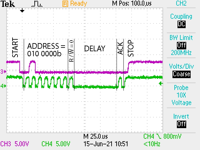
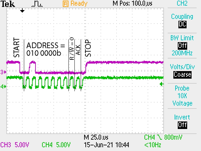
RUN: No data was transferred. Address only!!! Why?


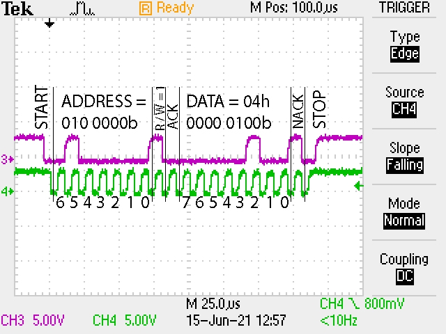
RUN STEP-BY-STEP - WORK!!!!
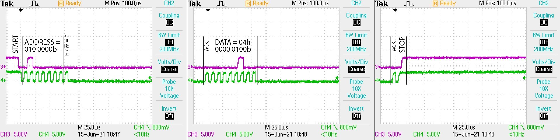
STEP-BY-STEP

RUN WITH DELAY:

//Transmit 
             mov.w #0020h,        &UCB0I2CSA                            ; I2C slave address = AD7998-0 (AS=Float)
             bis.b #UCTR,           &UCB0CTL1                             ; UCTR=1 -> I2C=TX
             BIS.B #UCTXSTT,   &UCB0CTL1                             ; Transmit START cond.

nnn:      BIT.B #UCB0TXIFG, &IFG2                                      ; UCB0TXIFG=1?
             JNC nnn

Wait      mov.w #01000,         R15                                           ; Delay to R15
L1         dec.w                        R15                                           ; Decrement R15
             jnz L1                                                                         ; Delay over?

             mov.b #04h,             &UCB0TXBUF                          ; 04h -> Tx
             BIS.B #UCTXSTP,   &UCB0CTL1                             ; transmit STOP cond

i2c_rdy bit.b #UCBBUSY,     &UCB0STAT                              ; wait until I2C module has finished all operations
             JC i2c_rdy

             JMP $        

No data was transferred. Address only!!! Why?

  • Hey! Anyone! Help! Please!!

  • Hi,

    Sorry for the late response. I am out of office last week.

    Do you have a actual I2C slave board with the slave address 0x20h connect to this master board when you do these tests? If you are not, it might cause this issue. The master only sends out the address and could not send the data until they get response from the slave.

    Best regards,

    Cash Hao

  • Yes. available!

    MSP430G2333+AD7998

    all screenshots are taken from an oscilloscope connected to AD7998

  • in the step-by-step debugger mode, after writing to the UCB0TXBUF register, when reading, I get the same data in the UCB0RXBUF register!

                          bic.b #UCTR, &UCB0CTL1             ; UCTR=0 -> I2C=RX
                          BIS.B #UCTXSTT,&UCB0CTL1      ; Transmit START cond.

    POLL_STT    BIT.B #UCTXSTT,&UCB0CTL1       ; Poll UCTXSTT bit
                          JC POLL_STT                                 ; When cleared,

                          mov.b UCB0RXBUF, R8
                          BIS.B #UCTXSTP,&UCB0CTL1       ; transmit STOP cond


    RUN I2C RX

    in Debugger UCB0RXBUF = 04h and R8=04h

    This means that the slave device is responding!

    And like this in the "run" mode - No data was transferred. Address only!!! After read -  UCB0RXBUF = 00h

  • Why does the master in write mode not generate data sending, but immediately starts the STOP procedure?

    And why does he do this in step-by-step debugging?

**Attention** This is a public forum