This thread has been locked.

If you have a related question, please click the "Ask a related question" button in the top right corner. The newly created question will be automatically linked to this question.

MSP430FR2422: Control GPIOs via SBW

Part Number: MSP430FR2422

Hello,

I'm trying to control the GPIOs of a MSP430FR2422 by writing to PAOUT / PADIR via Spy-bi-wire. However I'm only able to toggle four of the available pins: P1.4 - P1.7. On the rest of the pins, I can write to PAOUT / PADIR (and both registers reflect the correct value when reading them back) but the physical pins aren't driven to the correct value -- they're always 0 V.

It's very suspicious that the 4 pins that work are also the 4 JTAG pins, so I'm guessing all other GPIOs are disabled in JTAG mode. However the example code from slau320 suggests that it should be possible. In the screenshot below, the example code from slau320 flashes the LED by writing to P1OUT / P1DIR through JTAG.

Does anyone know whether it's possible to control MSP430 GPIOs while in JTAG mode?

Thanks,

David
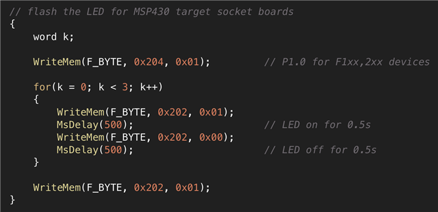
  • Does anyone know whether it's possible to control MSP430 GPIOs while in JTAG mode?

    Yes. For my old SBW+ flasher I used one extra GPIO (selected on the fly from available device package pins) for fast data transfer while target device is under SBW master control (not released / free running).

  • I'm trying to control the GPIOs of a MSP430FR2422 by writing to PAOUT / PADIR via Spy-bi-wire.

    From the MSP430FR4xx and MSP430FR2xx Family User's Guide (Rev. I) :

    8.3.1 Configuration After Reset After a BOR reset, all port pins are high-impedance with Schmitt triggers and their module functions disabled to prevent any cross currents. The application must initialize all port pins including unused ones (Section 8.3.2) as input high impedance, input with pulldown, input with pullup, output high, or output low according to the application needs by configuring PxDIR, PxREN, PxOUT, and PxIES accordingly. This initialization takes effect as soon as the LOCKLPM5 bit in the PM5CTL register (described in the PMM chapter) is cleared; until then, the I/Os remain in their high-impedance state with Schmitt trigger inputs disabled. Note that this is usually the same I/O initialization that is required after a wakeup from LPMx.5.

    A running program has to lock the port pins to allow them to be used, e.g. with:

        PM5CTL0 &= ~LOCKLPM5;                   // Disable the GPIO power-on default high-impedance mode
                                                // to activate previously configured port settings

    Suspect that for a MSP430FR2422, in JTAG mode you also need to clear the LOCKLPM5 bit.

  • That was it, all the pins are toggling now. Thanks so much!

**Attention** This is a public forum