This thread has been locked.

If you have a related question, please click the "Ask a related question" button in the top right corner. The newly created question will be automatically linked to this question.

EVM430-FR6043: Unable to get Tx data in Hyper Terminal

Part Number: EVM430-FR6043
Other Parts Discussed in Thread: MAX3232, MSP430FR6043

I'm testing uart protocol in EVM430-fr6043. I am not able to see the uart output in hyper terminal.

Board: EVM430 FR6043

Usb - Debug Interface : MSP - FET430UIF

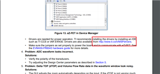
There is no serial port on board So i used TTL to Rs-232 converter using max3232 IC and RS-232 to usb converter using FT232RL. I check the output in hyper terminal but i not found any response from board. While Debugging the registers as shown as below picture. 

I'm new to this area. Please help me to solve this problem and thanks in advance.

  • Hi,

    Which code do you use?

    I think maybe you can use our example code: https://dev.ti.com/tirex/explore/node?node=AAA0cv-mSGNbvGcZLylxxw__IOGqZri__LATEST

    And actually, the EVM board include USB-TTL circuit, after you connect the EEVM to PC, you will find a application port.

    Thanks!

    Best Regards

    Johnson

  • Hello Sir,

    Thanks for your response. I'm not find application port after i connected to the evm430-fr6043 board. Instead of that it showing "MCU COMM HID to serial bridge" and "MSP Tools Drivers" in Other devices of Device manager as shown in screen shot. 

    Thanks,

    Ashok.

  • Hi,

    I think you don't install the driver normally, you can see my shot:

    You also can find the USRT Connext in J3.

    Thanks!

    Best Regards

    Johnson

  • Hello Sir,

    where can i download drivers to find the uart application port?

    I connected RXD and TXD in J3.

    Thanks,

    Ashok.

  • Hello sir,

    This is code i used with minor changes i.e. data=1.

    #include <msp430.h>
    #include "msp430fr6043.h"
    #include "stdint.h"

    uint8_t data=1;

    int main(void)
    {
    WDTCTL = WDTPW | WDTHOLD; // Stop Watchdog

    // Configure GPIO
    P1SEL0 |= (BIT2 | BIT3);
    P1SEL1 &= ~(BIT2 | BIT3); // USCI_A1 UART operation

    // Disable the GPIO power-on default high-impedance mode to activate
    // previously configured port settings
    PM5CTL0 &= ~LOCKLPM5;

    // Startup clock system with max DCO setting ~8MHz
    CSCTL0_H = CSKEY_H; // Unlock CS registers
    CSCTL1 = DCOFSEL_3 | DCORSEL; // Set DCO to 8MHz
    CSCTL2 = SELA__VLOCLK | SELS__DCOCLK | SELM__DCOCLK;
    CSCTL3 = DIVA__1 | DIVS__1 | DIVM__1; // Set all dividers
    CSCTL0_H = 0; // Lock CS registers

    // Configure USCI_A3 for UART mode
    UCA1CTLW0 = UCSWRST; // Put eUSCI in reset
    UCA1CTLW0 |= UCSSEL__SMCLK; // CLK = SMCLK
    // Baud Rate calculation
    // 8000000/(16*9600) = 52.083
    // Fractional portion = 0.083
    // User's Guide Table 24-4: UCBRSx = 0x04
    // UCBRFx = int ( (52.083-52)*16) = 1
    UCA1BRW = 52; // 8000000/16/9600
    UCA1MCTLW |= UCOS16 | UCBRF_1 | 0x4900;
    UCA1CTLW0 &= ~UCSWRST; // Initialize eUSCI
    UCA1IE |= UCRXIE; // Enable USCI_A3 RX interrupt

    while(!(UCA1IFG & UCTXIFG));
    UCA1TXBUF = data;

    __bis_SR_register(LPM3_bits + GIE); // Enter LPM3, interrupts enabled
    __no_operation(); // For debugger
    }

    #if defined(__TI_COMPILER_VERSION__) || defined(__IAR_SYSTEMS_ICC__)
    #pragma vector=EUSCI_A1_VECTOR
    __interrupt void USCI_A1_ISR(void)
    #elif defined(__GNUC__)
    void __attribute__ ((interrupt(EUSCI_A1_VECTOR))) USCI_A1_ISR (void)
    #else
    #error Compiler not supported!
    #endif
    {
    switch(__even_in_range(UCA1IV, USCI_UART_UCTXCPTIFG))
    {
    case USCI_NONE: break;
    case USCI_UART_UCRXIFG:
    while(!(UCA1IFG & UCTXIFG));
    UCA1TXBUF = UCA1RXBUF;
    __no_operation();
    break;
    case USCI_UART_UCTXIFG: break;
    case USCI_UART_UCSTTIFG: break;
    case USCI_UART_UCTXCPTIFG: break;
    default: break;
    }
    }

  • Hi, 

    Do you already install the driver normally? you can fine the link in EVM430-FR6043 user guide.

    This code should can trans the data that received, any problem?

    Best Regards

    Johnson

  • Hello sir,

    I installed drivers 

    Do you already install the driver normally? you can fine the link in EVM430-FR6043 user guide.

    I installed drivers. But after connecting my usb cable to pc I can't see the communication ports.

    This code should can trans the data that received, any problem?

    Code is fine. But when running code i'm getting the junk data in hyper terminal.

    Thanks,

    Ashok.

  • Hi,

    Does the baud are match with seeting?

    The seeting in this code is 9600.

    Best Regards

    Johnson

  • Hello sir,

    The seeting in this code is 9600.

    Baud rate is set as 9600 which is similar to code.

    Thanks,

    Ashok.

  • Hi Ashok,

    Do you have logiic analysis, if yes, maybe can capture the wave and try to find something.

    I will test this code in my side and go back.

    Thanks!

    Best Regards

    Johnson

  • Hello Sir,

    I don't have logic analyzer but i have oscilloscope. So i check at txd pin but it not captures exact data. I don't know whether it is problem of oscilloscope or Txd pin. 

    Thanks,

    Ashok.

  • Hi Ashok,

    Got it, I will test in my side and provide a code can run normal later.

    Thanks!

    Best Regards

    Johnson

  • Hi Ashok,

    Update the UART example code, and I tested is normal.

    #include <msp430.h>
    
    int main(void)
    {
        WDTCTL = WDTPW | WDTHOLD;               // Stop Watchdog
    
        // Configure GPIO
        P1SEL1 &= ~(BIT2 | BIT3);
        P1SEL0 |= BIT2 | BIT3;                  // USCI_A1 UART operation
    
        // Disable the GPIO power-on default high-impedance mode to activate
        // previously configured port settings
        PM5CTL0 &= ~LOCKLPM5;
    
        // Startup clock system with max DCO setting ~8MHz
        CSCTL0_H = CSKEY_H;                     // Unlock CS registers
        CSCTL1 = DCOFSEL_3 | DCORSEL;           // Set DCO to 8MHz
        CSCTL2 = SELA__VLOCLK | SELS__DCOCLK | SELM__DCOCLK;
        CSCTL3 = DIVA__1 | DIVS__1 | DIVM__1;   // Set all dividers
        CSCTL0_H = 0;                           // Lock CS registers
    
        // Configure USCI_A3 for UART mode
        UCA1CTLW0 = UCSWRST;                    // Put eUSCI in reset
        UCA1CTLW0 |= UCSSEL__SMCLK;             // CLK = SMCLK
        // Baud Rate calculation
        // 8000000/(16*9600) = 52.083
        // Fractional portion = 0.083
        // User's Guide Table 24-4: UCBRSx = 0x04
        // UCBRFx = int ( (52.083-52)*16) = 1
        UCA1BRW = 52;                           // 8000000/16/9600
        UCA1MCTLW |= UCOS16 | UCBRF_1 | 0x4900;
        UCA1CTLW0 &= ~UCSWRST;                  // Initialize eUSCI
        UCA1IE |= UCRXIE;                       // Enable USCI_A3 RX interrupt
    
        __bis_SR_register(LPM3_bits + GIE);     // Enter LPM3, interrupts enabled
        __no_operation();                       // For debugger
    }
    
    #if defined(__TI_COMPILER_VERSION__) || defined(__IAR_SYSTEMS_ICC__)
    #pragma vector=EUSCI_A1_VECTOR
    __interrupt void USCI_A1_ISR(void)
    #elif defined(__GNUC__)
    void __attribute__ ((interrupt(EUSCI_A1_VECTOR))) USCI_A1_ISR (void)
    #else
    #error Compiler not supported!
    #endif
    {
        switch(__even_in_range(UCA1IV, USCI_UART_UCTXCPTIFG))
        {
            case USCI_NONE: break;
            case USCI_UART_UCRXIFG:
                while(!(UCA1IFG&UCTXIFG));
                UCA1TXBUF = UCA1RXBUF;
                __no_operation();
                break;
            case USCI_UART_UCTXIFG: break;
            case USCI_UART_UCSTTIFG: break;
            case USCI_UART_UCTXCPTIFG: break;
            default: break;
        }
    }
    

    Thanks!

    Best Regards

    Johnson

  • Hello sir,

    Thank you for your suggestion. I tried this example code and got desired data at the hyper terminal. I tried with same data echo uart example using drivers library then i'm got nothing in the hyper terminal and also check whether the both are running with same speed (i.e. 9600).

    #include "driverlib.h"
    
    uint16_t i;
    uint8_t RXData = 0, TXData = 'A';
    uint8_t check = 0;
    
    void main(void)
    {
        // stop watchdog
        WDT_A_hold(WDT_A_BASE);


        //Set DCO frequency to 8 MHz
        CS_setDCOFreq(CS_DCORSEL_0,CS_DCOFSEL_3);
    
        CS_initClockSignal(CS_ACLK,CS_VLOCLK_SELECT,CS_CLOCK_DIVIDER_1);
    
        //Set SMCLK = DCO with frequency divider of 1
        CS_initClockSignal(CS_SMCLK,CS_DCOCLK_SELECT,CS_CLOCK_DIVIDER_1);
    
        //Set MCLK = DCO with frequency divider of 1
        CS_initClockSignal(CS_MCLK,CS_DCOCLK_SELECT,CS_CLOCK_DIVIDER_1);
    
    
        GPIO_setAsPeripheralModuleFunctionInputPin(
        GPIO_PORT_P1,
        GPIO_PIN2 + GPIO_PIN3,
        GPIO_SECONDARY_MODULE_FUNCTION
        );
    
        /*
         * Disable the GPIO power-on default high-impedance mode to activate
         * previously configured port settings
         */
        PMM_unlockLPM5();
    
        // Configure UART
        EUSCI_A_UART_initParam param = {0};
        param.selectClockSource = EUSCI_A_UART_CLOCKSOURCE_SMCLK;
        param.clockPrescalar = 52;
        param.firstModReg = 1;
        param.secondModReg = 0x49;
        param.parity = EUSCI_A_UART_NO_PARITY;
        param.msborLsbFirst = EUSCI_A_UART_LSB_FIRST;
        param.numberofStopBits = EUSCI_A_UART_ONE_STOP_BIT;
        param.uartMode = EUSCI_A_UART_MODE;
        param.overSampling = EUSCI_A_UART_OVERSAMPLING_BAUDRATE_GENERATION;
        
        if (STATUS_FAIL == EUSCI_A_UART_init(EUSCI_A1_BASE, &param)) {
            return;
        }
    
        EUSCI_A_UART_enable(EUSCI_A1_BASE);
    
        EUSCI_A_UART_clearInterrupt(EUSCI_A1_BASE,
          EUSCI_A_UART_RECEIVE_INTERRUPT);
    
        // Enable USCI_A0 RX interrupt
        EUSCI_A_UART_enableInterrupt(EUSCI_A1_BASE,
          EUSCI_A_UART_RECEIVE_INTERRUPT);                     // Enable interrupt
    
        __enable_interrupt();
        while (1)
        {
            //TXData = TXData+1;                      // Increment TX data
            // Load data onto buffer
            EUSCI_A_UART_transmitData(EUSCI_A1_BASE,
            				   TXData);
            while(check != 1);
            check = 0;
        }
    }
    //******************************************************************************
    //
    //This is the USCI_A0 interrupt vector service routine.
    //
    //******************************************************************************
    #if defined(__TI_COMPILER_VERSION__) || defined(__IAR_SYSTEMS_ICC__)
    #pragma vector=USCI_A1_VECTOR
    __interrupt
    #elif defined(__GNUC__)
    __attribute__((interrupt(USCI_A1_VECTOR)))
    #endif
    void USCI_A1_ISR(void)
    {
      switch(__even_in_range(UCA1IV,USCI_UART_UCTXCPTIFG))
      {
        case USCI_NONE: break;
        case USCI_UART_UCRXIFG:
          RXData = EUSCI_A_UART_receiveData(EUSCI_A1_BASE);
          if(!(RXData == TXData))                   // Check value
          {
            while(1);
          }
          check =1;
          break;
        case USCI_UART_UCTXIFG: break;
        case USCI_UART_UCSTTIFG: break;
        case USCI_UART_UCTXCPTIFG: break;
      }
    }
    

    Please guide me.

    Thanks,

    Ashok

  • Hi Ashok,

    Maybe you can debug this code and check if this code can enter the interrupt.

    Thanks!

    Best Regards

    Johnson

**Attention** This is a public forum