Other Parts Discussed in Thread: MSP430F1612
Hi,
I would like to know if this part, or other part of MCU is able to implement the GPIO control with excel VBA?
This will be helpful to build up auto testing environment using MCU for GPIO control
This thread has been locked.
If you have a related question, please click the "Ask a related question" button in the top right corner. The newly created question will be automatically linked to this question.
Hi,
I would like to know if this part, or other part of MCU is able to implement the GPIO control with excel VBA?
This will be helpful to build up auto testing environment using MCU for GPIO control
Other than my philosophical aversion to using excel for something like this, it is possible if you use a serial port and a Serial->USB converter. (If there is a launchpad, it should already have this) It is a relatively simple matter to get Excel to send serial commands, and the software on the MCU to receive serial commands and activate GPIO's is pretty easy.
Great thanks for your suggestion, now i am having EVMs of 430G2542 and G2553, may I ask that is receiving serial command is workable for these part number?
If it's able to work, can you help to suggest some information of example for reference?
It would be really helpful if there are examples to reference

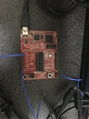
This is the EVM board I already have right now, it would be great if you can let me know the way to config this board to control by the UART command.
Great thanks for your help.
Jace H,
Great thanks for your suggestions also, now I would like to look to solutions to make 2553 or 2452 to receive UART command and control GPIO
It would be great if you can give me some direction to find the reference or the example.
Thanks a lot.
Your board should have a serial connection. Just go to Resource explorer and start with the PC echo UART example and use a PC terminal program like PuTTY to communicate with the board.
From there, you will need to figure out the VBA commands to talk to the serial terminal.
You will also have to modify the Echo program to do something with a received character.
like this pseudo code:
If rxchar == 'a'
{
//turnonGPIO1
}
if (rxchar == 'b'
{
//turn off GPIO1
}
I can't get more specific - and I hesitate to do that in case this is homework - because I don't know if you are using registers or DriverLib.
Gery,
Keith is pointing you to the right direction here. My only other comment would be that this Launchpad has a set of jumpers on the isolation block that must be configured in a certain way to allow for the HW UART (device peripheral - USCI) to be used instead of a timer based SW UART. Checkout the Launchpad User Guide for more information.
Hi Keith,
Great thanks for your help to guide, after searching for PuTTY, it should be able to control PC to send out serial command through MSP430F1612 from the board i already have, the i can program the MSP430G2553 to act (like GPIO or others)
After getting this part ready, the next step should be finding out how to make VBA control USB to send out serial command from 1612 to 2553, is this correct?
Please let me know if there are wrong understanding for building up this system.
Thanks a lot.
Hi Jace,
Thanks for the remind to config the SW UART to HW UART, but i am not really clear about that:
If i can make the upper part of EVM board to become and USB to serial(UART) block, I should still change the UART configuration?
Or what you really mean is that if i am going to use external UART signal to provide to 2553, i will need to change the UART configuration from SW to HW?
Great thanks for your help.
Hello Gary,
For the SW/HW configuration of UART within the isolation block on the launchpad, this connection is from the Target device (MSP430G2xxx) to the debugger, who routes it through the USB connection. By default, it is configured to connect to the pins for SW UART on the MSP430G2xx device, as that is what is used for the BSL. If you want to use the UART in your application, (aka the USCI or USART module), then you would need to switch these jumpers the HW configuration to route it thorugh the USB connection.
You will also need to double which pins the HW configuration connects to and what USCI/USART module is associated with those pins (e.g. USCI_A0, USCI_A1, etc.)
**Attention** This is a public forum