Other Parts Discussed in Thread: TMP1075, MSP430FR2433
Hi,
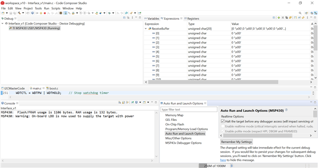
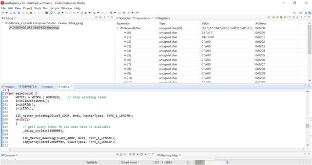
I'm currently trying to connect the MSP430G2ET to the TMP1075 via I2C communication. Below is my code that I'm using along with the output I'm seeing in Code Composer Studio, from my understanding I have to correct address for the TMP1075 but when I try to read the "Receive Buffer Value I'm only seeing 0x00. Is there another value that I should be reading or is there something wrong with how I am communicating via I2C?
//******************************************************************************
//   MSP430G2xx3 Demo - USCI_B0, I2C Master multiple byte TX/RX
//
//   Description: I2C master communicates to I2C slave sending and receiving
//   3 different messages of different length. I2C master will enter LPM0 mode
//   while waiting for the messages to be sent/receiving using I2C interrupt.
//   ACLK = NA, MCLK = SMCLK = DCO 16MHz.
//
//
//                   MSP430G2553         3.3V
//                 -----------------   /|\ /|\
//            /|\ |                 |   |  4.7k
//             |  |                 |  4.7k |
//             ---|RST              |   |   |
//                |                 |   |   |
//                |             P1.6|---|---+- I2C Clock (UCB0SCL)
//                |                 |   |
//                |             P1.7|---+----- I2C Data (UCB0SDA)
//                |                 |
//                |                 |
//
//   Nima Eskandari
//   Texas Instruments Inc.
//   April 2017
//   Built with CCS V7.0
//******************************************************************************

#include <msp430.h>
#include <stdint.h>
#include <stdbool.h>

//******************************************************************************
// Example Commands ************************************************************
//******************************************************************************

#define SLAVE_ADDR  0x48
#define CONVERSION_READY    0x10

/* CMD_TYPE_X_SLAVE are example commands the master sends to the slave.
 * The slave will send example SlaveTypeX buffers in response.
 *
 * CMD_TYPE_X_MASTER are example commands the master sends to the slave.
 * The slave will initialize itself to receive MasterTypeX example buffers.
 * */

#define CMD_TYPE_0_SLAVE      0
#define CMD_TYPE_1_SLAVE      1
#define CMD_TYPE_2_SLAVE      2

#define CMD_TYPE_0_MASTER      3
#define CMD_TYPE_1_MASTER      4
#define CMD_TYPE_2_MASTER      5

#define TYPE_0_LENGTH   1
#define TYPE_1_LENGTH   2
#define TYPE_2_LENGTH   6

#define MAX_BUFFER_SIZE     20

/* MasterTypeX are example buffers initialized in the master, they will be
 * sent by the master to the slave.
 * SlaveTypeX are example buffers initialized in the slave, they will be
 * sent by the slave to the master.
 * */

uint8_t MasterType2 [TYPE_2_LENGTH] = {'F', '4', '1', '9', '2', 'B'};
//uint8_t MasterType1 [TYPE_1_LENGTH] = { 8, 9};
uint8_t MasterType1 [TYPE_1_LENGTH] = { 0x00, 0xFF};
uint8_t MasterType0 [TYPE_0_LENGTH] = { 11};


uint8_t SlaveType2 [TYPE_2_LENGTH] = {0};
uint8_t SlaveType1 [TYPE_1_LENGTH] = {0};
uint8_t SlaveType0 [TYPE_0_LENGTH] = {0};

//******************************************************************************
// General I2C State Machine ***************************************************
//******************************************************************************


typedef enum I2C_ModeEnum{
    IDLE_MODE,
    NACK_MODE,
    TX_REG_ADDRESS_MODE,
    RX_REG_ADDRESS_MODE,
    TX_DATA_MODE,
    RX_DATA_MODE,
    SWITCH_TO_RX_MODE,
    SWITHC_TO_TX_MODE,
    TIMEOUT_MODE
} I2C_Mode;


/* Used to track the state of the software state machine*/
I2C_Mode MasterMode = IDLE_MODE;

/* The Register Address/Command to use*/
uint8_t TransmitRegAddr = 0;

/* ReceiveBuffer: Buffer used to receive data in the ISR
 * RXByteCtr: Number of bytes left to receive
 * ReceiveIndex: The index of the next byte to be received in ReceiveBuffer
 * TransmitBuffer: Buffer used to transmit data in the ISR
 * TXByteCtr: Number of bytes left to transfer
 * TransmitIndex: The index of the next byte to be transmitted in TransmitBuffer
 * */
uint8_t ReceiveBuffer[MAX_BUFFER_SIZE] = {0};
uint8_t RXByteCtr = 0;
uint8_t ReceiveIndex = 0;
uint8_t TransmitBuffer[MAX_BUFFER_SIZE] = {0};
uint8_t TXByteCtr = 0;
uint8_t TransmitIndex = 0;


/* I2C Write and Read Functions */

/* For slave device with dev_addr, writes the data specified in *reg_data
 *
 * dev_addr: The slave device address.
 *           Example: SLAVE_ADDR
 * reg_addr: The register or command to send to the slave.
 *           Example: CMD_TYPE_0_MASTER
 * *reg_data: The buffer to write
 *           Example: MasterType0
 * count: The length of *reg_data
 *           Example: TYPE_0_LENGTH
 *  */
I2C_Mode I2C_Master_WriteReg(uint8_t dev_addr, uint8_t reg_addr, uint8_t *reg_data, uint8_t count);

/* For slave device with dev_addr, read the data specified in slaves reg_addr.
 * The received data is available in ReceiveBuffer
 *
 * dev_addr: The slave device address.
 *           Example: SLAVE_ADDR
 * reg_addr: The register or command to send to the slave.
 *           Example: CMD_TYPE_0_SLAVE
 * count: The length of data to read
 *           Example: TYPE_0_LENGTH
 *  */
I2C_Mode I2C_Master_ReadReg(uint8_t dev_addr, uint8_t reg_addr, uint8_t count);
void CopyArray(uint8_t *source, uint8_t *dest, uint8_t count);


I2C_Mode I2C_Master_ReadReg(uint8_t dev_addr, uint8_t reg_addr, uint8_t count)
{
    /* Initialize state machine */
    MasterMode = TX_REG_ADDRESS_MODE;
    TransmitRegAddr = reg_addr;
    RXByteCtr = count;
    TXByteCtr = 0;
    ReceiveIndex = 0;
    TransmitIndex = 0;

    /* Initialize slave address and interrupts */
    UCB0I2CSA = dev_addr;
    IFG2 &= ~(UCB0TXIFG + UCB0RXIFG);       // Clear any pending interrupts
    IE2 &= ~UCB0RXIE;                       // Disable RX interrupt
    IE2 |= UCB0TXIE;                        // Enable TX interrupt

    UCB0CTL1 |= UCTR + UCTXSTT;             // I2C TX, start condition
    __bis_SR_register(CPUOFF + GIE);              // Enter LPM0 w/ interrupts

    return MasterMode;

}


I2C_Mode I2C_Master_WriteReg(uint8_t dev_addr, uint8_t reg_addr, uint8_t *reg_data, uint8_t count)
{
    /* Initialize state machine */
    MasterMode = TX_REG_ADDRESS_MODE;
    TransmitRegAddr = reg_addr;

    //Copy register data to TransmitBuffer
    CopyArray(reg_data, TransmitBuffer, count);

    TXByteCtr = count;
    RXByteCtr = 0;
    ReceiveIndex = 0;
    TransmitIndex = 0;

    /* Initialize slave address and interrupts */
    UCB0I2CSA = dev_addr;
    IFG2 &= ~(UCB0TXIFG + UCB0RXIFG);       // Clear any pending interrupts
    IE2 &= ~UCB0RXIE;                       // Disable RX interrupt
    IE2 |= UCB0TXIE;                        // Enable TX interrupt

    UCB0CTL1 |= UCTR + UCTXSTT;             // I2C TX, start condition
    __bis_SR_register(CPUOFF + GIE);              // Enter LPM0 w/ interrupts

    return MasterMode;
}


void CopyArray(uint8_t *source, uint8_t *dest, uint8_t count)
{
    uint8_t copyIndex = 0;
    for (copyIndex = 0; copyIndex < count; copyIndex++)
    {
        dest[copyIndex] = source[copyIndex];
    }
}


//******************************************************************************
// Device Initialization *******************************************************
//******************************************************************************


void initClockTo16MHz()
{
    if (CALBC1_16MHZ==0xFF)                  // If calibration constant erased
    {
        while(1);                               // do not load, trap CPU!!
    }
    DCOCTL = 0;                               // Select lowest DCOx and MODx settings
    BCSCTL1 = CALBC1_16MHZ;                    // Set DCO
    DCOCTL = CALDCO_16MHZ;
}

void initGPIO()
{
    P1DIR |= BIT0 + BIT1 + BIT2 + BIT3 + BIT4;
    P1OUT &= ~(BIT0 + BIT1 + BIT2 + BIT3 + BIT4);

    P1SEL |= BIT6 + BIT7;                     // Assign I2C pins to USCI_B0
    P1SEL2|= BIT6 + BIT7;                     // Assign I2C pins to USCI_B0
}

void initI2C()
{
    UCB0CTL1 |= UCSWRST;                      // Enable SW reset
    UCB0CTL0 = UCMST + UCMODE_3 + UCSYNC;     // I2C Master, synchronous mode
    UCB0CTL1 = UCSSEL_2 + UCSWRST;            // Use SMCLK, keep SW reset
    UCB0BR0 = 160;                            // fSCL = SMCLK/160 = ~100kHz
    UCB0BR1 = 0;
    UCB0I2CSA = SLAVE_ADDR;                   // Slave Address
    UCB0CTL1 &= ~UCSWRST;                     // Clear SW reset, resume operation
    UCB0I2CIE |= UCNACKIE;
}


//******************************************************************************
// Main ************************************************************************
// Send and receive three messages containing the example commands *************
//******************************************************************************

int main(void) {
    WDTCTL = WDTPW | WDTHOLD;    // Stop watchdog timer
    initClockTo16MHz();
    initGPIO();
    initI2C();

    I2C_Master_WriteReg(SLAVE_ADDR, 0x01, MasterType1, TYPE_1_LENGTH);
    while(1)
    {
        // poll every 100ms to see when data is available
        _delay_cycles(1600000);

        I2C_Master_ReadReg(SLAVE_ADDR, 0x00, TYPE_1_LENGTH);
        CopyArray(ReceiveBuffer, SlaveType1, TYPE_1_LENGTH);

        // Check status of conversion ready bit
        if(ReceiveBuffer[1] & CONVERSION_READY)
        {
            I2C_Master_ReadReg(SLAVE_ADDR, 0x00, TYPE_1_LENGTH);
            CopyArray(ReceiveBuffer, SlaveType1, TYPE_1_LENGTH);

            // Set break point here to examine results
            _no_operation();
        }
    }
}


//******************************************************************************
// I2C Interrupt For Received and Transmitted Data******************************
//******************************************************************************

#if defined(__TI_COMPILER_VERSION__) || defined(__IAR_SYSTEMS_ICC__)
#pragma vector = USCIAB0TX_VECTOR
__interrupt void USCIAB0TX_ISR(void)
#elif defined(__GNUC__)
void __attribute__ ((interrupt(USCIAB0TX_VECTOR))) USCIAB0TX_ISR (void)
#else
#error Compiler not supported!
#endif
{
  if (IFG2 & UCB0RXIFG)                 // Receive Data Interrupt
  {
      //Must read from UCB0RXBUF
      uint8_t rx_val = UCB0RXBUF;

      if (RXByteCtr)
      {
          ReceiveBuffer[ReceiveIndex++] = rx_val;
          RXByteCtr--;
      }

      if (RXByteCtr == 1)
      {
          UCB0CTL1 |= UCTXSTP;
      }
      else if (RXByteCtr == 0)
      {
          IE2 &= ~UCB0RXIE;
          MasterMode = IDLE_MODE;
          __bic_SR_register_on_exit(CPUOFF);      // Exit LPM0
      }
  }
  else if (IFG2 & UCB0TXIFG)            // Transmit Data Interrupt
  {
      switch (MasterMode)
      {
          case TX_REG_ADDRESS_MODE:
              UCB0TXBUF = TransmitRegAddr;
              if (RXByteCtr)
                  MasterMode = SWITCH_TO_RX_MODE;   // Need to start receiving now
              else
                  MasterMode = TX_DATA_MODE;        // Continue to transmision with the data in Transmit Buffer
              break;

          case SWITCH_TO_RX_MODE:
              IE2 |= UCB0RXIE;              // Enable RX interrupt
              IE2 &= ~UCB0TXIE;             // Disable TX interrupt
              UCB0CTL1 &= ~UCTR;            // Switch to receiver
              MasterMode = RX_DATA_MODE;    // State state is to receive data
              UCB0CTL1 |= UCTXSTT;          // Send repeated start
              if (RXByteCtr == 1)
              {
                  //Must send stop since this is the N-1 byte
                  while((UCB0CTL1 & UCTXSTT));
                  UCB0CTL1 |= UCTXSTP;      // Send stop condition
              }
              break;

          case TX_DATA_MODE:
              if (TXByteCtr)
              {
                  UCB0TXBUF = TransmitBuffer[TransmitIndex++];
                  TXByteCtr--;
              }
              else
              {
                  //Done with transmission
                  UCB0CTL1 |= UCTXSTP;     // Send stop condition
                  MasterMode = IDLE_MODE;
                  IE2 &= ~UCB0TXIE;                       // disable TX interrupt
                  __bic_SR_register_on_exit(CPUOFF);      // Exit LPM0
              }
              break;

          default:
              __no_operation();
              break;
      }
  }
}


//******************************************************************************
// I2C Interrupt For Start, Restart, Nack, Stop ********************************
//******************************************************************************

#if defined(__TI_COMPILER_VERSION__) || defined(__IAR_SYSTEMS_ICC__)
#pragma vector = USCIAB0RX_VECTOR
__interrupt void USCIAB0RX_ISR(void)
#elif defined(__GNUC__)
void __attribute__ ((interrupt(USCIAB0RX_VECTOR))) USCIAB0RX_ISR (void)
#else
#error Compiler not supported!
#endif
{
    if (UCB0STAT & UCNACKIFG)
    {
        UCB0STAT &= ~UCNACKIFG;             // Clear NACK Flags
    }
    if (UCB0STAT & UCSTPIFG)                        //Stop or NACK Interrupt
    {
        UCB0STAT &=
            ~(UCSTTIFG + UCSTPIFG + UCNACKIFG);     //Clear START/STOP/NACK Flags
    }
    if (UCB0STAT & UCSTTIFG)
    {
        UCB0STAT &= ~(UCSTTIFG);                    //Clear START Flags
    }
}