


Part Number: MSP430G2553
Hello,
and thanks for giving this question a read. In slau144, on page there's an OUT2 Signal. I was under the impression that every CCR register will have a corresponding output unit, which can output to a pin. At least, for the MSP430G2553's.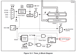
I looked at the pins to see where these might be and this seemed to be confirmed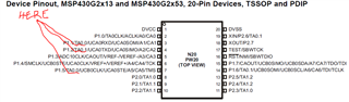
So now I type up some code to give me 2 different duty cycles, with no help from the CPU
#include <msp430.h>

/**
 * main.c
 */
int main(void)
{
	WDTCTL = WDTPW | WDTHOLD;	// stop watchdog timer


    BCSCTL1 = CALBC1_16MHZ;
    DCOCTL = CALDCO_16MHZ;

	// -------------------------- Pin Setup ------------------------
	P1DIR |= BIT2;
	P1SEL |= BIT2;

	P1DIR |= BIT5;
    P1SEL |= BIT5;
	//---------------------------- TIMER A Setup --------------------
	TACCR0 = 1023;
	TACCR1 = 127;
	TACCR2 = 512;

	TACCTL1 = OUTMOD_7;
	TA0CTL = TASSEL_2 + MC_1+ID_0;
	while(1){}

	return 0;
	}
GOOD NEWS! I see a pulse with the intended duty cycle on P1.2, bit P1.5 gives me nothing. I know i can get this behavior working with an interrupt, but I'd rather not use the CPU.
Anyone have any tips?
Thanks for looking this over.
~Triston

