This thread has been locked.
If you have a related question, please click the "Ask a related question" button in the top right corner. The newly created question will be automatically linked to this question.
Hello,
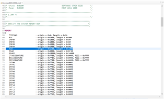
my software needs more than 4 Kbytes of RAM. LEA is not required. I would like to use the RAM of the LEA through the programme. Unfortunately, inexplicable changes of the content happen in this RAM area. I found this article: "">e2e.ti.com/.../msp430fr5994-can-i-combine-4kb-lea-ram-with-sram-into-a-single-8kb-block-of-ram". I was able to extend the RAM area. In the properties of the project in CodeComposerStudio, I entered the following in Build/MSP430-compiler/Predefined Simbols: MSP_DISABLE_LEA. Unfortunately, this did not help. Do I have to switch off the LEA directly? How does that work exactly?
Best Reagards
Hardy
Hi Hardy,
While the LEA module is running, the LEA data operations are performed on a shared 4KB of RAM out of the 8KB of total RAM
Some materials of LEA is in below
Low-Energy Accelerator (LEA) Commands Reference Guide
Low-Energy Accelerator (LEA) Registers Reference Guide
Low-Energy Accelerator (LEA) Common Parameter Blocks Reference Guide
If you don't use LEA RAM. You could define the RAM length and delete the define of LEA_RAM in .CMD file.
Hi Allen,
thank you for the quick reply. Unfortunately, it doesn't really help. I'll try to describe the problem in more detail using an example. The steps are also shown in the attached video. Deactivating the LEA in the project settings is shown in the photo. Is the deactivation done correctly?
In the example, the stack of the project is located in the upper 4 KB segment of the RAM. Four successive write operations with identical machine instructions in the stack are shown, which are carried out for parameter transfer in a function call. The first registers of the LEA can also be seen. It can be seen that the first and the 3rd write-oppation work. After the 2nd and 4th write operation, only the hi part of the 32-bit value can be seen on the stack. The memory cells to which the LO part belongs are unchanged. The sub-programme therefore receives incorrect values. Can you help me? What can I do to make it work?
Greatings
Hardy
Hi Hardy,
You could try to change the RAM length in .CMD file and delete related LEA RAM information.
Hi Allen,
yes, I did that. In my post above I wrote that it still doesn't work. The Lo part of the pointers is sometimes not written on the stack. Note on the video: You can see at one point that 16 times 0x11 are written to the stack. I do this by hand to show that through the MOVA commands sometimes only the Hi part (0x0000) is written and the Lo part remains unchanged. But the Lo part is important here.
Greating
Hardy
Hi Allen,
thanks for your help.
The programme is very long. I can't post the complete code. I will reduce the post to the part that shows the error. It is the call to a subroutine. The subroutine is passed 4 pointers. The pointers are stored on the stack. Putting them on the stack does not work. It is easiest to see in the assembler code. I describe the memory and the register contents.
1: 966 void savePosAndVelInSensors(float *lon, float *lat, unsigned int *alt, unsigned char *vel){
savePosAndVelInSensors(): // this is the head of the function
2: 042864: 00B1 0010 SUBA #0x00010,SP // SP: 0x003BD0
3: 042868: 0F71 000C MOVA R15,0x000c(SP) // SP: 0x003BC0, R15: 0x002A60
4: 04286c: 0E71 0008 MOVA R14,0x0008(SP) // R14: 0x003BDE
5: 042870: 0D71 0004 MOVA R13,0x0004(SP) // R13: 0x003BDA
6: 042874: 0C71 0000 MOVA R12,0x0000(SP) // R12: 0x003BD6
7: 968 itoha((uint8_t*)lon,(uint8_t*)&sensors.lon[1],4); // this is the first line inner the function...
8: 042878: 008D 5383 MOVA #0x05383,R13
After executing line 2, I write to memory by hand:
0x003BC0: 11 11 11 11 11 11 11 11 11 11 11 11 11 11 11 11
The memory (stack) changes as follows:
After line 3:
0x003BC0: 11 11 11 11 11 11 11 11 11 11 11 11 11 11 00 00
After line 4:
0x003BC0: 11 11 11 11 11 11 11 11 11 11 00 00 11 11 00 00
After line 5:
0x003BC0: 11 11 11 11 DA 3B 00 00 11 11 00 00 11 11 00 00
After line 6:
0x003BC0: 11 11 00 00 DA 3B 00 00 11 11 00 00 11 11 00 00
It can be seen that in this attempt the contents of registers 15, 14 and 12 do not arrive completely on the stack. Only the content of register 13 is completely written to the stack. In other attempts, other registers are written and others are not.
The content of LEACNF0 is 0x00000001. The programme section is not interrupted by an interrupt. I can show the phenomenon in a video conference.
Is it possible to check what the content of the DMA destination address is at that particular time? Is it possible that a DMA write to another RAM area is preventing the CPU from writing?
I can work around the problem by not passing the parameters through the stack. But then I don't know if the programme is unstable in other places. That's why I think finding the cause is important.
Greatigs
Hardy
Hi Allen,
thanks for your help.
The programme is very long. I can't post the complete code. I will reduce the post to the part that shows the error. It is the call to a subroutine. The subroutine is passed 4 pointers. The pointers are stored on the stack. Putting them on the stack does not work. It is easiest to see in the assembler code. I describe the memory and the register contents.
1: 966 void savePosAndVelInSensors(float *lon, float *lat, unsigned int *alt, unsigned char *vel){
savePosAndVelInSensors(): // this is the head of the function
2: 042864: 00B1 0010 SUBA #0x00010,SP // SP: 0x003BD0
3: 042868: 0F71 000C MOVA R15,0x000c(SP) // SP: 0x003BC0, R15: 0x002A60
4: 04286c: 0E71 0008 MOVA R14,0x0008(SP) // R14: 0x003BDE
5: 042870: 0D71 0004 MOVA R13,0x0004(SP) // R13: 0x003BDA
6: 042874: 0C71 0000 MOVA R12,0x0000(SP) // R12: 0x003BD6
7: 968 itoha((uint8_t*)lon,(uint8_t*)&sensors.lon[1],4); // this is the first line inner the function...
8: 042878: 008D 5383 MOVA #0x05383,R13
After executing line 2, I write to memory by hand:
0x003BC0: 11 11 11 11 11 11 11 11 11 11 11 11 11 11 11 11
The memory (stack) changes as follows:
After line 3:
0x003BC0: 11 11 11 11 11 11 11 11 11 11 11 11 11 11 00 00
After line 4:
0x003BC0: 11 11 11 11 11 11 11 11 11 11 00 00 11 11 00 00
After line 5:
0x003BC0: 11 11 11 11 DA 3B 00 00 11 11 00 00 11 11 00 00
After line 6:
0x003BC0: 11 11 00 00 DA 3B 00 00 11 11 00 00 11 11 00 00
It can be seen that in this attempt the contents of registers 15, 14 and 12 do not arrive completely on the stack. Only the content of register 13 is completely written to the stack. In other attempts, other registers are written and others are not.
The content of LEACNF0 is 0x00000001. The programme section is not interrupted by an interrupt. I can show the phenomenon in a video conference.
Is it possible to check what the content of the DMA destination address is at that particular time? Is it possible that a DMA write to another RAM area is preventing the CPU from writing?
I can work around the problem by not passing the parameters through the stack. But then I don't know if the programme is unstable in other places. That's why I think finding the cause is important.
edit:
I have noticed a connection with a DMA channel. This is triggered by a UART and writes the received byte into another RAM area. This writing works. If I disable this controller during the execution of lines 3, 4, 5 and 6 above, the execution of the MOVA commands of lines 3, 4, 5 and 6 will work.
However, the DMA operation is needed.
How can I ensure that the stack operations work without errors?
Greatigs
Hardy
Hi Hardy
Modify the .cmd file like this extend the RAM to 8K and remove all the LEA information
/****************************************************************************** * * Copyright (C) 2012 - 2020 Texas Instruments Incorporated - http://www.ti.com/ * * Redistribution and use in source and binary forms, with or without * modification, are permitted provided that the following conditions * are met: * * Redistributions of source code must retain the above copyright * notice, this list of conditions and the following disclaimer. * * Redistributions in binary form must reproduce the above copyright * notice, this list of conditions and the following disclaimer in the * documentation and/or other materials provided with the * distribution. * * Neither the name of Texas Instruments Incorporated nor the names of * its contributors may be used to endorse or promote products derived * from this software without specific prior written permission. * * THIS SOFTWARE IS PROVIDED BY THE COPYRIGHT HOLDERS AND CONTRIBUTORS * "AS IS" AND ANY EXPRESS OR IMPLIED WARRANTIES, INCLUDING, BUT NOT * LIMITED TO, THE IMPLIED WARRANTIES OF MERCHANTABILITY AND FITNESS FOR * A PARTICULAR PURPOSE ARE DISCLAIMED. IN NO EVENT SHALL THE COPYRIGHT * OWNER OR CONTRIBUTORS BE LIABLE FOR ANY DIRECT, INDIRECT, INCIDENTAL, * SPECIAL, EXEMPLARY, OR CONSEQUENTIAL DAMAGES (INCLUDING, BUT NOT * LIMITED TO, PROCUREMENT OF SUBSTITUTE GOODS OR SERVICES; LOSS OF USE, * DATA, OR PROFITS; OR BUSINESS INTERRUPTION) HOWEVER CAUSED AND ON ANY * THEORY OF LIABILITY, WHETHER IN CONTRACT, STRICT LIABILITY, OR TORT * (INCLUDING NEGLIGENCE OR OTHERWISE) ARISING IN ANY WAY OUT OF THE USE * OF THIS SOFTWARE, EVEN IF ADVISED OF THE POSSIBILITY OF SUCH DAMAGE. * * Default linker command file for Texas Instruments MSP430FR5994 * *****************************************************************************/ /******************************************************************************/ /* */ /* Usage: lnk430 <obj files...> -o <out file> -m <map file> lnk.cmd */ /* cl430 <src files...> -z -o <out file> -m <map file> lnk.cmd */ /* */ /*----------------------------------------------------------------------------*/ /* These linker options are for command line linking only. For IDE linking, */ /* you should set your linker options in Project Properties */ /* -c LINK USING C CONVENTIONS */ /* -stack 0x0100 SOFTWARE STACK SIZE */ /* -heap 0x0100 HEAP AREA SIZE */ /* */ /*----------------------------------------------------------------------------*/ /* 1.209 */ /*----------------------------------------------------------------------------*/ /****************************************************************************/ /* SPECIFY THE SYSTEM MEMORY MAP */ /****************************************************************************/ MEMORY { TINYRAM : origin = 0xA, length = 0x16 BSL : origin = 0x1000, length = 0x800 INFOD : origin = 0x1800, length = 0x80 INFOC : origin = 0x1880, length = 0x80 INFOB : origin = 0x1900, length = 0x80 INFOA : origin = 0x1980, length = 0x80 RAM : origin = 0x1C00, length = 0x2000 FRAM : origin = 0x4000, length = 0xBF80 FRAM2 : origin = 0x10000,length = 0x34000 JTAGSIGNATURE : origin = 0xFF80, length = 0x0004, fill = 0xFFFF BSLSIGNATURE : origin = 0xFF84, length = 0x0004, fill = 0xFFFF IPESIGNATURE : origin = 0xFF88, length = 0x0008, fill = 0xFFFF INT00 : origin = 0xFF90, length = 0x0002 INT01 : origin = 0xFF92, length = 0x0002 INT02 : origin = 0xFF94, length = 0x0002 INT03 : origin = 0xFF96, length = 0x0002 INT04 : origin = 0xFF98, length = 0x0002 INT05 : origin = 0xFF9A, length = 0x0002 INT06 : origin = 0xFF9C, length = 0x0002 INT07 : origin = 0xFF9E, length = 0x0002 INT08 : origin = 0xFFA0, length = 0x0002 INT09 : origin = 0xFFA2, length = 0x0002 INT10 : origin = 0xFFA4, length = 0x0002 INT11 : origin = 0xFFA6, length = 0x0002 INT12 : origin = 0xFFA8, length = 0x0002 INT13 : origin = 0xFFAA, length = 0x0002 INT14 : origin = 0xFFAC, length = 0x0002 INT15 : origin = 0xFFAE, length = 0x0002 INT16 : origin = 0xFFB0, length = 0x0002 INT17 : origin = 0xFFB2, length = 0x0002 INT18 : origin = 0xFFB4, length = 0x0002 INT19 : origin = 0xFFB6, length = 0x0002 INT20 : origin = 0xFFB8, length = 0x0002 INT21 : origin = 0xFFBA, length = 0x0002 INT22 : origin = 0xFFBC, length = 0x0002 INT23 : origin = 0xFFBE, length = 0x0002 INT24 : origin = 0xFFC0, length = 0x0002 INT25 : origin = 0xFFC2, length = 0x0002 INT26 : origin = 0xFFC4, length = 0x0002 INT27 : origin = 0xFFC6, length = 0x0002 INT28 : origin = 0xFFC8, length = 0x0002 INT29 : origin = 0xFFCA, length = 0x0002 INT30 : origin = 0xFFCC, length = 0x0002 INT31 : origin = 0xFFCE, length = 0x0002 INT32 : origin = 0xFFD0, length = 0x0002 INT33 : origin = 0xFFD2, length = 0x0002 INT34 : origin = 0xFFD4, length = 0x0002 INT35 : origin = 0xFFD6, length = 0x0002 INT36 : origin = 0xFFD8, length = 0x0002 INT37 : origin = 0xFFDA, length = 0x0002 INT38 : origin = 0xFFDC, length = 0x0002 INT39 : origin = 0xFFDE, length = 0x0002 INT40 : origin = 0xFFE0, length = 0x0002 INT41 : origin = 0xFFE2, length = 0x0002 INT42 : origin = 0xFFE4, length = 0x0002 INT43 : origin = 0xFFE6, length = 0x0002 INT44 : origin = 0xFFE8, length = 0x0002 INT45 : origin = 0xFFEA, length = 0x0002 INT46 : origin = 0xFFEC, length = 0x0002 INT47 : origin = 0xFFEE, length = 0x0002 INT48 : origin = 0xFFF0, length = 0x0002 INT49 : origin = 0xFFF2, length = 0x0002 INT50 : origin = 0xFFF4, length = 0x0002 INT51 : origin = 0xFFF6, length = 0x0002 INT52 : origin = 0xFFF8, length = 0x0002 INT53 : origin = 0xFFFA, length = 0x0002 INT54 : origin = 0xFFFC, length = 0x0002 RESET : origin = 0xFFFE, length = 0x0002 } /****************************************************************************/ /* Specify the LEA memory map */ /****************************************************************************/ //#define LEASTACK_SIZE 0x138 //MEMORY //{ // LEARAM : origin = 0x2C00, length = 0x1000 - LEASTACK_SIZE // LEASTACK : origin = 0x3C00 - LEASTACK_SIZE, length = LEASTACK_SIZE //} /****************************************************************************/ /* SPECIFY THE SECTIONS ALLOCATION INTO MEMORY */ /****************************************************************************/ SECTIONS { GROUP(RW_IPE) { GROUP(READ_WRITE_MEMORY) { .TI.persistent : {} /* For #pragma persistent */ .cio : {} /* C I/O Buffer */ .sysmem : {} /* Dynamic memory allocation area */ } PALIGN(0x0400), RUN_START(fram_rw_start) GROUP(IPENCAPSULATED_MEMORY) { .ipestruct : {} /* IPE Data structure */ .ipe : {} /* IPE */ .ipe_const : {} /* IPE Protected constants */ .ipe:_isr : {} /* IPE ISRs */ } PALIGN(0x0400), RUN_START(fram_ipe_start) RUN_END(fram_ipe_end) RUN_END(fram_rx_start) } > 0x4000 .cinit : {} > FRAM /* Initialization tables */ .binit : {} > FRAM /* Boot-time Initialization tables */ .pinit : {} > FRAM /* C++ Constructor tables */ .init_array : {} > FRAM /* C++ Constructor tables */ .mspabi.exidx : {} > FRAM /* C++ Constructor tables */ .mspabi.extab : {} > FRAM /* C++ Constructor tables */ .text:_isr : {} > FRAM /* Code ISRs */ #ifndef __LARGE_DATA_MODEL__ .const : {} > FRAM /* Constant data */ #else .const : {} >> FRAM | FRAM2 /* Constant data */ #endif #ifndef __LARGE_CODE_MODEL__ .text : {} > FRAM /* Code */ #else .text : {} >> FRAM2 | FRAM /* Code */ #endif #ifdef __TI_COMPILER_VERSION__ #if __TI_COMPILER_VERSION__ >= 15009000 #ifndef __LARGE_CODE_MODEL__ .TI.ramfunc : {} load=FRAM, run=RAM, table(BINIT) #else .TI.ramfunc : {} load=FRAM | FRAM2, run=RAM, table(BINIT) #endif #endif #endif .jtagsignature : {} > JTAGSIGNATURE .bslsignature : {} > BSLSIGNATURE GROUP(SIGNATURE_SHAREDMEMORY) { .ipesignature : {} /* IPE Signature */ .jtagpassword : {} /* JTAG Password */ } > IPESIGNATURE .bss : {} > RAM /* Global & static vars */ .data : {} > RAM /* Global & static vars */ .TI.noinit : {} > RAM /* For #pragma noinit */ .stack : {} > RAM (HIGH) /* Software system stack */ .tinyram : {} > TINYRAM /* Tiny RAM */ /* MSP430 INFO memory segments */ .infoA : type = NOINIT{} > INFOA .infoB : type = NOINIT{} > INFOB .infoC : type = NOINIT{} > INFOC .infoD : type = NOINIT{} > INFOD // .leaRAM : {} > LEARAM /* LEA RAM */ // .leaStack : {} > LEASTACK (HIGH) /* LEA STACK */ /* MSP430 interrupt vectors */ .int00 : {} > INT00 .int01 : {} > INT01 .int02 : {} > INT02 .int03 : {} > INT03 .int04 : {} > INT04 .int05 : {} > INT05 .int06 : {} > INT06 .int07 : {} > INT07 .int08 : {} > INT08 .int09 : {} > INT09 .int10 : {} > INT10 .int11 : {} > INT11 .int12 : {} > INT12 .int13 : {} > INT13 .int14 : {} > INT14 .int15 : {} > INT15 .int16 : {} > INT16 .int17 : {} > INT17 LEA : { * ( .int18 ) } > INT18 type = VECT_INIT PORT8 : { * ( .int19 ) } > INT19 type = VECT_INIT PORT7 : { * ( .int20 ) } > INT20 type = VECT_INIT EUSCI_B3 : { * ( .int21 ) } > INT21 type = VECT_INIT EUSCI_B2 : { * ( .int22 ) } > INT22 type = VECT_INIT EUSCI_B1 : { * ( .int23 ) } > INT23 type = VECT_INIT EUSCI_A3 : { * ( .int24 ) } > INT24 type = VECT_INIT EUSCI_A2 : { * ( .int25 ) } > INT25 type = VECT_INIT PORT6 : { * ( .int26 ) } > INT26 type = VECT_INIT PORT5 : { * ( .int27 ) } > INT27 type = VECT_INIT TIMER4_A1 : { * ( .int28 ) } > INT28 type = VECT_INIT TIMER4_A0 : { * ( .int29 ) } > INT29 type = VECT_INIT AES256 : { * ( .int30 ) } > INT30 type = VECT_INIT RTC_C : { * ( .int31 ) } > INT31 type = VECT_INIT PORT4 : { * ( .int32 ) } > INT32 type = VECT_INIT PORT3 : { * ( .int33 ) } > INT33 type = VECT_INIT TIMER3_A1 : { * ( .int34 ) } > INT34 type = VECT_INIT TIMER3_A0 : { * ( .int35 ) } > INT35 type = VECT_INIT PORT2 : { * ( .int36 ) } > INT36 type = VECT_INIT TIMER2_A1 : { * ( .int37 ) } > INT37 type = VECT_INIT TIMER2_A0 : { * ( .int38 ) } > INT38 type = VECT_INIT PORT1 : { * ( .int39 ) } > INT39 type = VECT_INIT TIMER1_A1 : { * ( .int40 ) } > INT40 type = VECT_INIT TIMER1_A0 : { * ( .int41 ) } > INT41 type = VECT_INIT DMA : { * ( .int42 ) } > INT42 type = VECT_INIT EUSCI_A1 : { * ( .int43 ) } > INT43 type = VECT_INIT TIMER0_A1 : { * ( .int44 ) } > INT44 type = VECT_INIT TIMER0_A0 : { * ( .int45 ) } > INT45 type = VECT_INIT ADC12_B : { * ( .int46 ) } > INT46 type = VECT_INIT EUSCI_B0 : { * ( .int47 ) } > INT47 type = VECT_INIT EUSCI_A0 : { * ( .int48 ) } > INT48 type = VECT_INIT WDT : { * ( .int49 ) } > INT49 type = VECT_INIT TIMER0_B1 : { * ( .int50 ) } > INT50 type = VECT_INIT TIMER0_B0 : { * ( .int51 ) } > INT51 type = VECT_INIT COMP_E : { * ( .int52 ) } > INT52 type = VECT_INIT UNMI : { * ( .int53 ) } > INT53 type = VECT_INIT SYSNMI : { * ( .int54 ) } > INT54 type = VECT_INIT .reset : {} > RESET /* MSP430 reset vector */ } /****************************************************************************/ /* MPU/IPE SPECIFIC MEMORY SEGMENT DEFINITONS */ /****************************************************************************/ #ifdef _IPE_ENABLE #define IPE_MPUIPLOCK 0x0080 #define IPE_MPUIPENA 0x0040 #define IPE_MPUIPPUC 0x0020 // Evaluate settings for the control setting of IP Encapsulation #if defined(_IPE_ASSERTPUC1) #if defined(_IPE_LOCK ) && (_IPE_ASSERTPUC1 == 0x08)) fram_ipe_enable_value = (IPE_MPUIPENA | IPE_MPUIPPUC |IPE_MPUIPLOCK); #elif defined(_IPE_LOCK ) fram_ipe_enable_value = (IPE_MPUIPENA | IPE_MPUIPLOCK); #elif (_IPE_ASSERTPUC1 == 0x08) fram_ipe_enable_value = (IPE_MPUIPENA | IPE_MPUIPPUC); #else fram_ipe_enable_value = (IPE_MPUIPENA); #endif #else #if defined(_IPE_LOCK ) fram_ipe_enable_value = (IPE_MPUIPENA | IPE_MPUIPLOCK); #else fram_ipe_enable_value = (IPE_MPUIPENA); #endif #endif // Segment definitions #ifdef _IPE_MANUAL // For custom sizes selected in the GUI fram_ipe_border1 = (_IPE_SEGB1>>4); fram_ipe_border2 = (_IPE_SEGB2>>4); #else // Automated sizes generated by the Linker fram_ipe_border2 = fram_ipe_end >> 4; fram_ipe_border1 = fram_ipe_start >> 4; #endif fram_ipe_settings_struct_address = Ipe_settingsStruct >> 4; fram_ipe_checksum = ~((fram_ipe_enable_value & fram_ipe_border2 & fram_ipe_border1) | (fram_ipe_enable_value & ~fram_ipe_border2 & ~fram_ipe_border1) | (~fram_ipe_enable_value & fram_ipe_border2 & ~fram_ipe_border1) | (~fram_ipe_enable_value & ~fram_ipe_border2 & fram_ipe_border1)); #endif #ifdef _MPU_ENABLE #define MPUPW (0xA500) /* MPU Access Password */ #define MPUENA (0x0001) /* MPU Enable */ #define MPULOCK (0x0002) /* MPU Lock */ #define MPUSEGIE (0x0010) /* MPU Enable NMI on Segment violation */ __mpu_enable = 1; // Segment definitions #ifdef _MPU_MANUAL // For custom sizes selected in the GUI mpu_segment_border1 = _MPU_SEGB1 >> 4; mpu_segment_border2 = _MPU_SEGB2 >> 4; mpu_sam_value = (_MPU_SAM0 << 12) | (_MPU_SAM3 << 8) | (_MPU_SAM2 << 4) | _MPU_SAM1; #else // Automated sizes generated by Linker #ifdef _IPE_ENABLE //if IPE is used in project too //seg1 = any read + write persistent variables //seg2 = ipe = read + write + execute access //seg3 = code, read + execute only mpu_segment_border1 = fram_ipe_start >> 4; mpu_segment_border2 = fram_rx_start >> 4; mpu_sam_value = 0x1573; // Info R, Seg3 RX, Seg2 RWX, Seg1 RW #else mpu_segment_border1 = fram_rx_start >> 4; mpu_segment_border2 = fram_rx_start >> 4; mpu_sam_value = 0x1513; // Info R, Seg3 RX, Seg2 R, Seg1 RW #endif #endif #ifdef _MPU_LOCK #ifdef _MPU_ENABLE_NMI mpu_ctl0_value = MPUPW | MPUENA | MPULOCK | MPUSEGIE; #else mpu_ctl0_value = MPUPW | MPUENA | MPULOCK; #endif #else #ifdef _MPU_ENABLE_NMI mpu_ctl0_value = MPUPW | MPUENA | MPUSEGIE; #else mpu_ctl0_value = MPUPW | MPUENA; #endif #endif #endif /****************************************************************************/ /* INCLUDE PERIPHERALS MEMORY MAP */ /****************************************************************************/ -l msp430fr5994.cmd
Test by defining a large array, you could see the .map file after building. The RAM is 8K and used 1fe2
****************************************************************************** MSP430 Linker PC v20.2.0 ****************************************************************************** >> Linked Wed Sep 15 19:30:39 2021 OUTPUT FILE NAME: <MSP430FR5994.out> ENTRY POINT SYMBOL: "_c_int00_noargs_mpu" address: 00004000 MEMORY CONFIGURATION name origin length used unused attr fill ---------------------- -------- --------- -------- -------- ---- -------- TINYRAM 0000000a 00000016 00000000 00000016 RWIX BSL 00001000 00000800 00000000 00000800 RWIX INFOD 00001800 00000080 00000000 00000080 RWIX INFOC 00001880 00000080 00000000 00000080 RWIX INFOB 00001900 00000080 00000000 00000080 RWIX INFOA 00001980 00000080 00000000 00000080 RWIX RAM 00001c00 00002000 00001fe2 0000001e RWIX FRAM 00004000 0000bf80 00000042 0000bf3e RWIX JTAGSIGNATURE 0000ff80 00000004 00000004 00000000 RWIX ffff BSLSIGNATURE 0000ff84 00000004 00000004 00000000 RWIX ffff IPESIGNATURE 0000ff88 00000008 00000008 00000000 RWIX ffff INT00 0000ff90 00000002 00000000 00000002 RWIX INT01 0000ff92 00000002 00000000 00000002 RWIX INT02 0000ff94 00000002 00000000 00000002 RWIX INT03 0000ff96 00000002 00000000 00000002 RWIX
You could have a try on it. If you have other problem, you could submit a new ticket.
Hi Allen,
I made the recommended settings before the test. The result was the use of the upper address range in RAM by the linker. This can be seen in the displayed values of the stack pointer and the registers 12, 13 and 14 in my last post. The problem is: Why is only the HI part of the registers written to RAM? Why does this only happen sometimes and not with every write operation within the same c-code line?
As requested, I will open a new ticket about this.
Greatings
Hardy
My last test showed that the problem is due to the incorrect execution of a machine command under certain conditions. It also occurs in the lower RAM range. So it can't be the LEA. It is ok if you close this ticket.
**Attention** This is a public forum