This thread has been locked.

If you have a related question, please click the "Ask a related question" button in the top right corner. The newly created question will be automatically linked to this question.

MSP430FR6047: Problem that waveform is attenuated depending on the transmission frequency setting in Design Center

Guru 14830 points

Part Number: MSP430FR6047
Other Parts Discussed in Thread: EVM430-FR6043, EVM430-FR6047

Hi, 

I have a question about the USS received waveform.

Fig. 1 shows the waveform confirmed at the Design Center with the transmission frequency set to 526kHz and Fig. 2 set the transmission frequency to 260kHz.
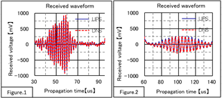
When I checked the waveform when the transmission frequency was set to 526kHz with an oscilloscope, it was 47.7mVp-p. The waveform when the transmission frequency was set to 260 kHz was 43.6 mVp-p, and no relatively large difference was observed.

Is there any processing that attenuates the input signal depending on the transmission frequency setting conditions before the gain amplification of the received wave input signal?
If so, is it possible to change the filter settings, source code, etc. to solve the current problem?

Thanks,

Koki

  • Hello Koki,

    Some things to consider.

    • There is a filter on the output on the EVM along with an impedance matching resistor (200 ohms) 
    • Please validate the receive gain is the same in both situations as there is a PGA that could affect the amplitude of the TX signal in the design center vs. scope. The design center only looks at receive.
    • May want to change the 200 ohm impedance matching resistor if there is a difference in impedance between the 500kHz and 200kHz transducers. The transducer datasheet should have that information. 

    I would also like to point you to the following MSP Academy around USS Water Meters to help guide you on your development and testing: https://dev.ti.com/tirex/explore/node?node=AP3BtYCoe9uXZzBARBtGhA__IOGqZri__LATEST 

  • Hi,

    May want to change the 200 ohm impedance matching resistor if there is a difference in impedance between the 500kHz and 200kHz transducers. The transducer datasheet should have that information. 

    At 500kHz and 200kHz, the transducer has not changed. If there is no specification in the data sheet, what criteria should be used to change the impedance matching resistance value?

    Koki

  • Koki,

    Transducers are typically centered around a specific frequency. My assumption here is you are using a 500kHz transducer and trying to run it at 200kHz. If that is the case, then you will see signal degradation. You will need a different transducer to operate at that output frequency. 

  • Hi, Jace H

    My assumption here is you are using a 500kHz transducer and trying to run it at 200kHz. If that is the case, then you will see signal degradation.

    The problems I have now are as follows.

    When looking at the waveform at the design center, the received wave is attenuated depending on the frequency.

    However, when the received wave was confirmed with an oscilloscope, no attenuation of the waveform was observed regardless of the frequency.

    The reason why this phenomenon occurs has not been clarified yet.

    Thanks,

  • Koki,

    You need to utilize different transducers for different frequencies. The transducers only operate properly within the correct resonance frequency of the transducer. You may also have to adjust passives on the board in order to impedance match each transducer and adjust filters to properly receive the signal . 

  • Hi, Jace H

    You need to utilize different transducers for different frequencies. The transducers only operate properly within the correct resonance frequency of the transducer.

    The resonance frequencies are as follows.
     -The resonance frequency at 526kHz is 570kHz.
     -The resonance frequency at 260kHz is 250kHz.

    When I checked the received wave with an oscilloscope, no attenuation was seen. However, when I checked it at the design center, I saw some attenuation.

    You may also have to adjust passives on the board in order to impedance match each transducer and adjust filters to properly receive the signal . 

    Please tell me how to adjust the filter of the received wave.

    Also which value should be used as a reference for adjusting the impedance resistance?

    Thanks,

  • Hello Koki,

    I've been corrected by a colleague that there isn't a filter on the output. You just need to adjust the resistor to match the impedance of your transducer.

    I am still confused that you are only utilizing one transducer here though. Although possible, it is unexpected to have one transducer give a good response at both 500kHz and 250 kHz. Please perform a frequency sweep of your transducer so you can see the peak frequencies. You can find out more about doing this in the gui via section 3.1.3.1 in the following app note/reference design: Optimizing Ultrasonic Sensing Metrology Reference Design for Water Flow Measurement

    I would also encourage you to utilize this document and the MSP Academy I linked to earlier to continue developing your design. 

  • Koki,

    Another data point that I missed is that you are utilizing the water library with quite low frequencies. Typically, water utilizes 1MHz or 2MHz transducers. As such, there are some bandpass filters for water enabled by default. These are defined in USS_SW_LIB_APP_FILTER_COEFFICIENTS in the USS_userConfig.h file. You may want to turn these off as well due to the frequencies you are using. 

  • Hi, Jace H

    May want to change the 200 ohm impedance matching resistor if there is a difference in impedance between the 500kHz and 200kHz transducers. The transducer datasheet should have that information. 

    Where should I look in the transducer data sheet? The model numbers of the transducers are listed below.
      - Transducer Maker: Fuji Ceramics
      - Model: 0.25Z5D-LYX (C-6)
      - Nominal frequency: 250kHz

    I am still confused that you are only utilizing one transducer here though. Although possible, it is unexpected to have one transducer give a good response at both 500kHz and 250 kHz. Please perform a frequency sweep of your transducer so you can see the peak frequencies.

    I'm sorry for my lack of explanation. The transducer is changed according to the frequency.
     -When the transmission frequency is 526kHz, a transducer with a resonance frequency of 570kHz is used.
     -When the transmission frequency is 260kHz, a transducer with a resonance frequency of 250kHz is used.


    These are defined in USS_SW_LIB_APP_FILTER_COEFFICIENTS in the USS_userConfig.h file. You may want to turn these off as well due to the frequencies you are using. 

    Try disabling the filter to see if the situation improves. We will give you feedback as soon as we know the result.


    -------------

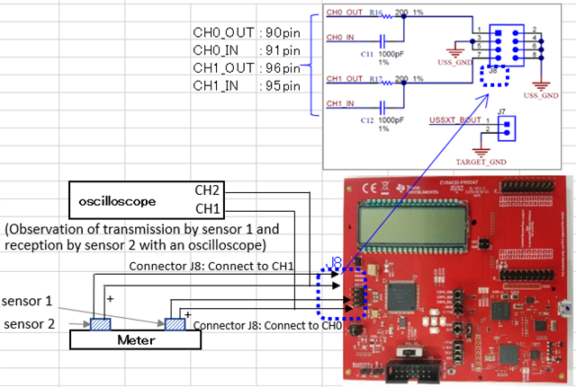
    I am checking the received wave with an oscilloscope. It is connected as follows.

    When the frequency is 260kHz, there is a problem that the received wave cannot be confirmed when the sensor cable of the received wave is connected to the EVM connector.


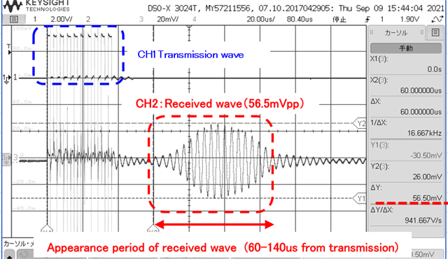
    Transmission: Driven by EVM
    Reception: Observe by removing the reception cable of sensor 2 from EVM

    ■There is no problem with both transmitted and received waves.


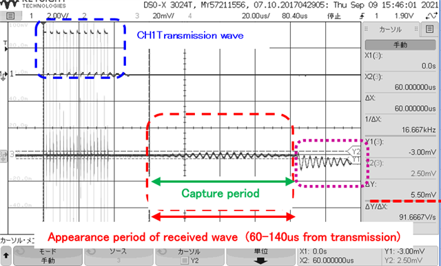
    Transmission: Driven by EVM
    Reception: Observe by connecting the reception cable of sensor 2 to EVM

    Capture start: 60us, Capture period: 80us

    ■The result is that the received wave cannot be confirmed during the period when the received wave should appear.

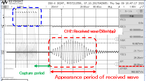
    Transmission: Driven by EVM
    Reception: Observe by connecting the reception cable of sensor 2 to EVM

    Capture start: 30us, Capture period: 30us

    The GUI settings are as follows.

    --------------GUI parameter------------------

    Transmit frequency=260kHz

    Number of pulse =10

    Gap between pulse start and ADC capture=60

    Capture Duration=80us

    GUI Based Gain Control=750db

    UPS0 to UPS1 Gap=20ms

    ---------------------------------------------------

    In the confirmation result of the transmission frequency 526kHz (Capture setting start = 30us, period = 65us, gain setting = 26.7dB), there was no significant difference in the appearance of the received wave depending on whether or not the EVM was connected to the sensor connector.

    On the other hand, in the case of 260kHz, the appearance of the received wave depends on the Capture end timing according to the Capture setting (start, period) of the evaluation board GUI.

    Please let me know if you have any opinion on whether the above difference occurs depending on the frequency.

    Thanks,

  • Hi Koki,

    I'm confused by what you are trying to do here. Can you give us some more information about the water application you are trying to implement? The water metering example application is designed for transducers in the 1MHz to 2.5MHz range.  Is there a reason why you are evaluating this platform with 260kHz transducers?  The settings you provided above aren't possible with our platform. For example, 750dB is not a gain option. Is this a typo?

    BR,
    Leo

  • Hi, Leo

    I'm so sorry for the late contact.

    The settings you provided above aren't possible with our platform. For example, 750dB is not a gain option. Is this a typo?

    I'm sorry, it's a typo.
    The correct configuration parameters are:

    --------------parameter------------------

    Transmit frequency=260kHz

    Number of pulse =10

    Gap between pulse start and ADC capture=60us

    Capture Duration=80us

    GUI Based Gain Control=30.8db

    GUI Based Gain Control=750us

    UPS0 to UPS1 Gap=20ms

    ------------------------------------------------


    I'm confused by what you are trying to do here. Can you give us some more information about the water application you are trying to implement?

    Currently, we are evaluating a prototype flow meter.

    Each characteristic of the transmission / reception parameters is being evaluated, but the transmission frequency depends on the structural specifications of the ultrasonic detector.

    By changing the frequency, the frequency at which the received wave is maximized is set as the transmission frequency (currently about 260kHz).

    Therefore, at present, we are using a transducer with a resonance frequency that is close to the set transmission frequency.


    We also evaluated EVM430-FR6043.

    I was able to confirm the received wave on the evaluation board, but I decided to suspend the evaluation by EVM430-FR6043 and proceed with the evaluation by EVM430-FR6047 for the following reasons.

    -----------------------

    a. EVM430-FR6043 has a higher fixed amplification degree of EVM than EVM430-FR6047. From the comparison of the verification results, it is estimated that the EVM430-FR6043 has a fixed amplifier circuit in the EVM for the input signal before amplifying with the set gain in the GUI tool. Is this perception correct? Therefore, the amplification of the input signal cannot be managed only by the gain set by the GUI tool, and the base noise is also amplified.

    b. FR6047 is more convenient because we want to evaluate at a large sampling frequency. Compared to EVM430-FR6047, EVM430-FR6043 has a smaller maximum possible setting value of measurement sampling frequency. (6047: 4MHz, 6043: 2MHz)

    -----------------------

    Thanks,

    Koki

  • Hi, 

    If you have any update, please let me know.

    Thanks,

  • Hi Koki,

    I recommend that you use the FR6043 platform when evaluating lower frequency transducers with a sampling frequency of 1MHz for 200kHz and 2MHz for 500kHz as described in the documentation. You should reduce the gain of the external amplifier by changing the values of the feedback resistors as needed.  The FR6047 platform(and software) is configured for higher frequency transducers.  You can also use the FR6043 platform for higher frequency water transducer evaluation by configuring the platform for water meter applications as described here:

    https://www.ti.com/tool/TIDM-02005?keyMatch=&tisearch=search-everything&usecase=refdesign

    The FR6043 is also capable of multi-tone excitation while the FR6047 is not. This may be an important feature for your evaluation.

    BR,
    Leo

**Attention** This is a public forum