This thread has been locked.

If you have a related question, please click the "Ask a related question" button in the top right corner. The newly created question will be automatically linked to this question.

MSP430G2553: power consumption strange.

Part Number: MSP430G2553
Other Parts Discussed in Thread: MSP-EXP430G2ET, MSP430FR6972, , ENERGYTRACE

Hi guys!

I've an strange power consumption:

I've an msp-exp430G2ET with an MSP430G2553 mcu. I've also an MSP430FR6972 MCU

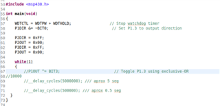
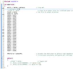
I've too a dummy program that's only a wile(1) loop

Msp430G2 version:
Msp430FR version:
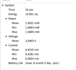
If I flash the FR version in MSP430FR6972 mcu I get this energy trace info:
And if I measure externaly I obtain 0.44mA
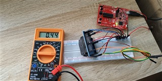
Perfect!!!!

Then I do the same experiment with MSP430G2553 mcu (and his dummy program version) and I get  this Energy trace values
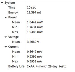
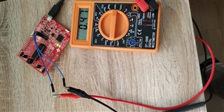
If I measure the power consumption at the Launchpad pins I get 0.47 mA:
But in the experiment of FR I can't used the Launchpad mcu socket. I used the Jumper Isolation block to configure an independent MCU.  Thus I do the same with G2. I put the MSP430G2 mcu on a protoboard  whithout external clock, reser circuit... nothig just VC and VS (same FR)
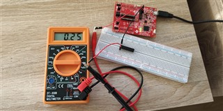
Wowww!!!!! My power consumption is only 0.25mA!!!!!!

Please!!! I have 2 questions:

  1. Why I obtain half power consumption when I use the protoboard?????
  2. In the datasheet we see that power consumption of FR6972 mcu is 100uA/Mhz in runmode, and the power consumption of G2553 is 230uA/Mhz (more than double of FR). The Why in the same conditions the real power consumption of FR is 0.44mA and the power consumption of G2 is 0.25mA?? if it's true he G2 mcu is very more efficient than FR!!!

Anyone have any explanation? please!!! I don't understand!

Thanxs Slight smile

P.D. I configured FR6972 mcu:

GND pin isolation from launchpad -> pin mcu: 17,62,39,50,53,56,(6 unhused datashee recomendation, I tested open also)
3V pin isolation from launchad -> pin mcu: 18,63,40,49

I configured G2 mcu

GND pin isolation from launchpad -> pin mcu: 20
3V pin isolation from launchad -> pin mcu: 1

  • Hi Sacha,

    To make sure I'm understanding your setup:

    - G2xx: On protoboard, not connected to debugger. Seeing 0.25mA.

    - FR69xx: Not sure about the setup for this. It seems like you are connected to the debugger since you are able to use EnergyTrace? Can you further clarify/provide an image?

    If you are connected to the debugger for the FR69xx, one possible explanation for the difference you are seeing between the FR69xx and the G2xx is due to the power management module (PMM). In the FR69xx family, the Vcore regulator can operate in high-performance (used in active and LPM0/1 modes) and low-power mode (LPM2/3/4 modes). However, when the FR69xx is plugged into the debugger, high-performance mode is automatically used. In general, if you want to take accurate power measurements, you should take them with the device completely disconnected from the debugger since the JTAG subsystem within the debugger is also drawing power.

    Also, here's an app report on migrating from the MSP430G2xx to the MSP430FR69xx families that goes into detail on the key differences between the 2 families [link].

    Thanks,

    Urica Wang

  • Hi Urica, I explain it.

    When I get Energy trace information both MCU (G2 and FR69) are connected to GND, 3v3, RDX, TXD, SBWTDIO and SBWTCK pins of msp-exp430G2ET pin isolation block to Flash, Debug and get energy trace information.

    After that I exit of debug mode, flash again mcu program and disconect USB and remove  RDX,TXD, SBWTDIO and SBWTCK to get the standalone measurement. Only GND and 3v3 pins of launchpad are used. Then I connect USB and measure the intensity. The ammeter is connected to 3V3 pin.

    Same operation for both MCUs

    So, In Energy trace measurement GND, 3v3, RDX, TXD, SBWTDIO and SBWTCK pins of msp-exp430G2ET pin isolation block are connected to Mcu

    In Standalone measurement: only GND and 3V3 pins of msp-exp430G2ET pin isolation block are connected to Mcu, The ammeter in connected between 3v3 pin isolation block of launchpad and the Mcu.

    Urica,thanks about link. i didn't know this document ;)

  • Hi Sacha,

    Thanks for clarifying. Can you verify the frequencies for both devices and where the program and data is stored for the FR69xx device?

    Based on the datasheets, I see that the active mode current at 1MHz when Vcc = 3 V has a typical value of 330 uA and a max of 420 uA for the G2xx device. For the FR69xx, the active mode current at 1MHz when Vcc = 3 V (with typical program execution where program and data reside entirely in FRAM) has a typical value of 210 uA.

    Thanks,

    Urica Wang

  • Thanxs Urica!!!!! You're the best!!!!!

    The problem was the frequences. By default G2 runs at 1Mhz but FR6972 runs at 8Mhz. Also by default CCS store the program in FRam and the data in Ram. 
    Runing FR at 1Mhz I get a real measurent of 0.30mA

    Thanxs

**Attention** This is a public forum