This thread has been locked.

If you have a related question, please click the "Ask a related question" button in the top right corner. The newly created question will be automatically linked to this question.

MSP430F249: The device does not boot normally during the reset operation

Guru 12285 points
Part Number: MSP430F249


Hi,

I have a question in the continuation of the E2E thread below.

https://e2e.ti.com/support/microcontrollers/msp-low-power-microcontrollers-group/msp430/f/msp-low-power-microcontroller-forum/1037124/msp430f249-what-happens-when-the-high-signal-is-input-to-the-reset-pin-after-the-mcu-is-powered-on


[Question1]

MSP430x2xx Family User's Guide (Rev. J) --2.2.1.1 Reset / NMI Pin has the following text.

------
If the RST / NMI pin is set to the reset function, the CPU is held in the reset state as long as the RST / NMI pin is held low. After the input changes to a high state, the CPU starts program execution at the word address stored in the reset vector, 0FFFEh, and the RSTIFG flag is set.
----------

From this sentence, I think that the CPU cannot start the program when the High signal (it has not been set to the Low signal in advance) is input to the RESET terminal.

Is this perception wrong? Also, please tell me the behavior of the MCU at this time. (The MCU operates uncertainty. Memory corruption may occur, etc.)

[Question2]

A reset IC is connected to the RST pin, and the reset duration is 7 ms. In this case, can the reset operation and the BOR operation interfere with each other?  Is there any uncertainty operation such as memory corruption?
Since either reset or BOR works, I don't think it will interfere.
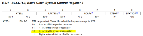
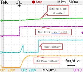
[Question3]

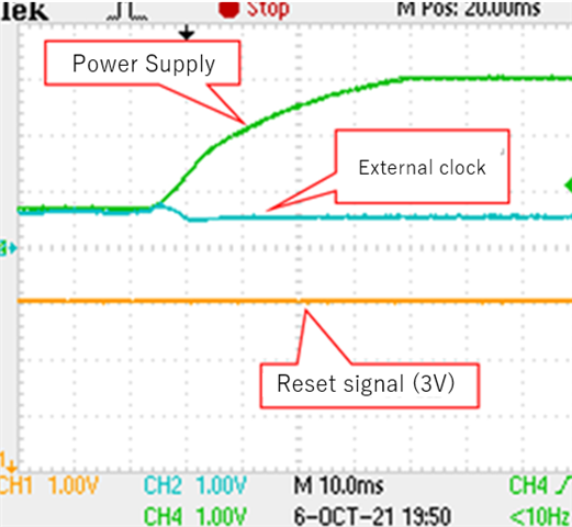
If the voltage of the reset terminal is High when the power is applied to the MCU, may the DCO and watchdog not start?

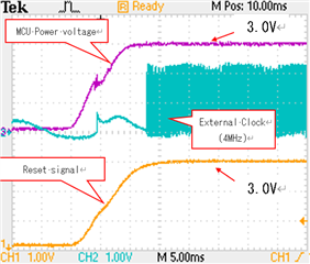
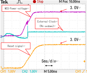
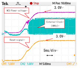
This is for the case where the voltage of the reset terminal is High when the power is applied to the MCU. After that, the external clock oscillates after the reset input voltage changes from Low to High.

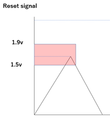
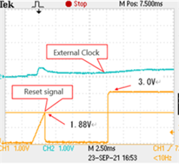
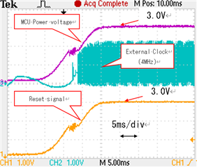
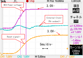
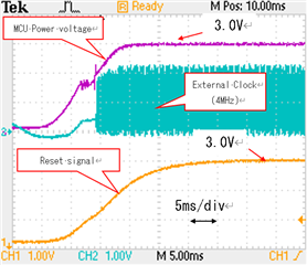
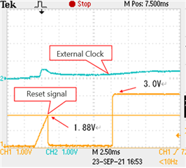
As shown in the figure below, when the reset voltage is 1.7V or less when the microcomputer is started, the external clock oscillates and the microcomputer operates.

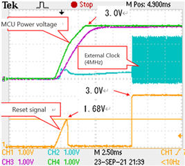
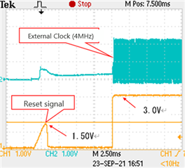
It may not oscillate.

In this case, the reset input voltage when starting the MCU is 1.88V.

We are very sorry, but we would like an answer as soon as possible.

Best regards,

Koki

  • Hi Koki,

    Page 40 and 41 of the datasheet provide voltage and timing specifications for the SVS and BOR. Is it possible to control the timing of the power up for the reset controller you are using? Which device are you using to control the reset line?  

    BR,
    Leo

  • Hi, Leo

    Is it possible to control the timing of the power up for the reset controller you are using?

    Yes.

    When power is supplied to the MCU, the external clock may oscillate or the external clock may not oscillate.

    If it is started with 3V applied to the reset terminal, the probability of not operating is about 90%. Each waveform is shown below.

    [When oscillating]


    [When not oscillating]

    If the external clocks (XIN, XOUT) do not work, are DCO and BOR not working? If you have any advice or suggestions, please let me know.

    Which device are you using to control the reset line?  

    I will confirm and inform you of the model number of the reset IC.

    Thanks,

    Koki

  • Hi Koki,

    I'm trying to understand what you are seeing between the voltage on the reset line and the clock starting(or not starting). When the voltage on the reset line is less than 1.7V before reset, does the clock start only 9 out of 10 times?

    BR,
    Leo

  • Hi, Leo

    Which device are you using to control the reset line? 

    The model number of the reset IC is BD5227G from Rohm.


    I will talk about the peak voltage of the reset signal when the MCU is started.

    Due to the specifications of the reset IC, the peak voltage of the reset signal fluctuates as shown in the following waveform.

    ・ 1.5V or less ・ ・ ・ Normal operation


    ・ 1.5v ~ 1.9v ・ ・ ・ Does not start normally and the external clock does not oscillate.

    I would like to know the reason why the MCU does not start when the reset signal is 1.5 to 1.8V.

    Thanks,

    Koki

  • Hi Koki,

    The only relevant errata I see is this one:

    BCL13 BCL Module Category Functional Function DCO powerup halt Description

    When subject to very slow Vcc rise times, the device may enter into a state where the DCO does not oscillate. No JTAG access or program execution is possible and the device will remain in a reset state until the supply voltage is disconnected.

    Workaround Apply a Vcc poweron ramp >= 10V/second under all power-on/power-cycle scenarios.

    But it looks like you're VCC poweron ramp should be fast enough. One thing that I saw in the datasheet is that the threshold for the SVS is 1.7V.  I'm wondering if the issue you are seeing might be related to that. 

    Beyond these observations, it's not clear to me why this might be happening.

    BR,
    Leo

  • I'm Kenji inquiring about MSP430F249 to Koki.

    I am using MSP430F249.

    I mounted the MSP430F249 on another board and tested it, but it didn't output the external clock XOUT after powering up.

    The test was performed with 10 kΩ connected to the RST pin of the MSP430F249.
    The test then started the MSP430F249 when I connected the RST pin of the MSP430F249 to GND.
    Why doesn't MSP430F249 start first?
  • Hi Kenji,

    If you have the reset pin configured for reset(not NMI), when you pull the reset pin to GND, the device is in reset.  How long are you keeping the reset line down before letting it go back to VCC? What value capacitor do you have on the reset line?

    Do you have a scope capture of VCC with respect to the reset line? 

    BR,

    Leo

  • Hi Leo,

    Thank you for the answer.

    I will give you the answer to your question.

    It goes down for 15ms before returning the reset line to VCC.

    There are no capacitors on the reset line.

    I will tell you about scope capture next time.

    Thanks,

    Kenji

  • Hi,Leo

    I attach the voltage waveform.

    It goes down for 9ms before returning the reset line to VCC.

    The figure below shows the time when the external clock does not oscillate.

    It goes down for 9ms before returning the reset line to VCC.

    The above figure shows the case where the MCU is mounted on the product board.

    The figure below shows a single MCU and a 4MHz oscillator mounted on an experimental board.

    The figure below shows a 10kΩ resistor connected to the reset input terminal between VCC.

    Please tell me the reason why the external clock does not oscillate.

    Thanks,

    Kenji

  • Hi Kenji,

    We typically recommend a 47K pull up resistor. Do you see the same issue with this value?

    BR,
    Leo

  • Hi,Leo

    The figure below shows the waveform when the external clock does not oscillate when the 47kΩ resistor is pulled up.

    The probability that the external clock will not oscillate is higher than when a 10kΩ resistor is pulled up.

    The figure below shows the waveform when an external clock oscillates when a 47kΩ resistor is pulled up.

    Thanks,

    Kenji

  • Hi Kenji,

    The target board schematic for this device is found in fig. B-44 of the guide below.  Could you also add the 10nF on reset and see if behavior changes?

    https://www.ti.com/lit/ug/slau278ah/slau278ah.pdf

    BR,
    Leo

  • Hi,Leo

    The external clock sometimes did not oscillate when 10nF was connected to the reset input.

    The probability that the external clock will not oscillate is about 80%.

    The figure below shows the waveform when the external clock does not oscillate.

    The figure below shows the waveform when the external clock oscillates.

    This was also done when 100nF was connected to the reset input, but the external clock sometimes did not oscillate.

    The figure below shows the waveform when the external clock does not oscillate at that time.

    The figure below shows the waveform when the external clock oscillates at that time.

    Thanks,

    Kenji

  • Hi,Leo

    We confirmed the probability of oscillation of the external clock by changing the slope of the MCU power supply voltage.

    The measurement was performed with a 47kΩ resistor connected between the reset input and the power supply.No capacitor is connected.

    When the inclination is slower than 1.5ms / 3V, the external clock may not oscillate.

    The figure below is a graph of test results.

    When a capacitor 10nF was added to the reset input, it sometimes did not oscillate when it was slower than 1.4ms / 3V.

    The figure below is a graph of test results.

    When the slope of the MCU power supply voltage is slower than 1.4ms / 3V, may the external clock not oscillate?

    Thanks,

    Kenji

  • Hi Kenji,

    It's not clear to me what is causing this behavior. Is it possible to enable a faster rise time of VCC in your design? I would propose reducing the capacitance on VCC to ensure that you get a faster rise in VCC. 

    BR,
    Leo

  • Hi,Leo

    It is not possible to shorten the rise time of VCC.

    This is because the rise time varies depending on the customer who uses the product.

    I reported last time that the external clock did not oscillate when the slope of the power supply voltage was 3.2ms / 3V.

    At that time, I confirmed today that the external clock oscillates if the reset input is Low when the microcomputer is started.

    The method was done by connecting a 100nF capacitor between the reset input terminal and GND.

    From these results, it is considered that the MCU may not operate POR due to the slope of the power supply voltage.

    Therefore, should the reset input of the MCU be set to Low when power is supplied?

    Thanks,

    Kenji

  • Hi Kenji,

    I would expect that when the recommended capacitance and resistance is applied to the reset line, the device should come out of reset normally. With the recommended resistance and capacitance on the reset line, the device may be  energized by VCC before the capacitor on the reset line is charged. 

    BR,

    Leo

  • Hi,Leo

    I think that the POR operates and the external clock oscillates even if the reset input has no capacitance.

    However, the external clock may not oscillate due to the slope of the MCU power supply voltage.

    Please tell me the conditions under which POR does not work.

    Is it necessary to connect a capacitance to the reset input to ensure that the external clock oscillates?

    Thanks,

    Kenji

  • Hi Kenji,

    I'm referring you back to the original thread cited at the beginning of this thread:

    https://e2e.ti.com/support/microcontrollers/msp-low-power-microcontrollers-group/msp430/f/msp-low-power-microcontroller-forum/1037124/msp430f249-what-happens-when-the-high-signal-is-input-to-the-reset-pin-after-the-mcu-is-powered-on

    From this thread, you can see that the conditions required for POR are explained in section 2.2.1.1 of the family user's guide. I'm not seeing any errata related to POR for this device.  I don't have any documentation beyond the family user's guide, the datasheet, and errata to determine the conditions under which the POR does not work.

    Please also excuse my delay in responses as I'm currently on vacation.

    BR,
    Leo

  • Hi,Leo

    I understand the POR conditions and errata.

    As a result of checking the logic of WDTNMI, when the external clock oscillated, it was Low when the power was supplied, but it became High after the power was supplied.

    On the other hand, when the external clock did not oscillate, it was low when the power was supplied, but it continued to be low even after the power was supplied.

    Is the reason why the external clock does not start is that WDTNMI keeps low?

    I don't know why WDTNMI stays low.

    Please tell me the reason why WDTNMI keeps low.

    I would be happy if the cause could be found and the problems so far could be solved.

    Thanks,

    Kenji

  • Hi Kenji,

    I recommend you create a new thread on this topic so that you can get more timely responses.  If you look at Figure 2-9 of the user's guide for this device, you'll see that the Watchdog timer and oscillator faults can both effect the state of the processor.  

    BR,
    Leo

  • Hi Kenji,

    Can you confirm that you are using 4MHz crystal connected to XT2 pins?

    If you notice in one of your captures, XT2 starts up well before VCC has reached 3.0v.

    Since the XT2 driver is disabled at POR and software must enable it, this indicates that the CPU is operational and executing code at that point early in time.  Have you tried putting a 5 or 10ms software delay before enabling this bit allowing VCC to reach its full 3.0v?

    Also, there are several settings for crystal drive strength.  Can you confirm you are using '10' for XT2Sx?

  • Hi,Leo

    The relationship with the watchdog timer will be inquired separately.

    The 4MHz clock is connected to Xin, not XT2.

    The actual circuit uses a reset IC and provides a reset time of 10ms when power is supplied.

    Also, the Xin and XT2 settings are set to 10.

    Next, I checked whether the main clock DCO was operating when the power was turned on, but when the Xin clock did not oscillate, the main clock DCO did not oscillate.

    I don't understand why the main clock DCO does not oscillate.

    As I told you the other day, it may not oscillate depending on the power supply.

    Please tell me the reason why it does not oscillate.

    Also, I would like you to confirm the same thing.

    Thanks,

    Kenji

  • Hi,Leo

    The circuit diagram around the MSU is shown.

    The 4MHz clock is connected to the MCU's Xin and Xout.

    The figure below shows the waveform when the Main Clock does not oscillate.

    The signal that the Main Clock is operating was output to P2.0 and monitored.

    A transistor is connected to P2.0 and it is output by an open collector.

    When the voltage is Hi, the Main Clock does not oscillate.

    The figure below shows the waveform when the main clock is oscillating.

    When the main clock does not oscillate, it depends on the slope of the power supply voltage of the MCU, as previously reported.

    As previously contacted, it depends on the voltage of the reset signal before the 3V was generated in the power supply voltage of the MCU.

    From the above results, is it because POR does not start when the reset voltage becomes Hi voltage before supplying 3V to the power supply voltage of the MCU?

    In this case, does the main clock not oscillate without being reset by POR?

    Thanks,

    Kenji

**Attention** This is a public forum