


Hello,
I'd like to use the external bias pin to set the bias on an external op amp, as in the gas evaluation kit. In the reference design, there is a no pop option for using the external bias pin. Could you please confirm the recommended circuit here. See schematic snapshot below from the TI reference design:
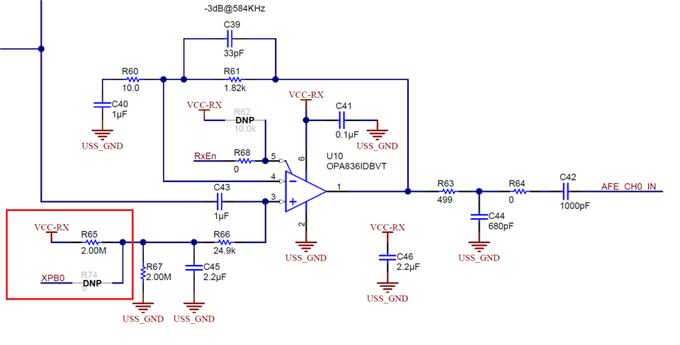
I'm assuming to use the XPB0 option, we would populate R47 and depopulate R65. Is that correct? Is there anything else that should be done here?
Thanks in advance for the help!


