This thread has been locked.

If you have a related question, please click the "Ask a related question" button in the top right corner. The newly created question will be automatically linked to this question.

MSP430F67771A: RTC_C module lags time after MCU main power off even with battery connected

Part Number: MSP430F67771A

Hi All,

we are facing RTC_C module time lagging issue with some of the production units,

I am using MSP430F67771a MCU in my product and facing time lag issue when main power is cut off.

As per TI document,

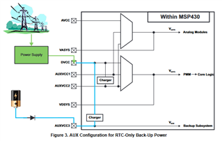
When Mains is available, DVCC allows AUXVCC3 to be powered from mains,
which is more than sufficient to supply AUXVCC3. When there is a power outage, the battery then powers
AUXVCC3 and keeps the RTC functional, despite the rest of the chip not having power.

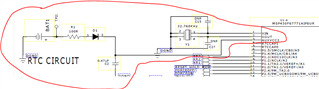
In our hardware design/schematics battery is connected to AUXVCC3 pin of MCU.

The RTC software configuration is mentioned below

ACLK = 32.768kHz, MCLK = SMCLK 1.048 MHz

//clock init

  UCSCTL6 &= ~(XT1OFF);                     // XT1 On
  UCSCTL6 |= XCAP_1;                        // Internal load cap
 
//  do
//  {
//    UCSCTL7 &= ~(XT2OFFG + XT1LFOFFG + DCOFFG);
//                                            // Clear XT2,XT1,DCO fault flags
//    SFRIFG1 &= ~OFIFG;                      // Clear fault flags
//  }while (SFRIFG1&OFIFG);                   // Test oscillator fault flag

  UCSCTL6 &= ~(XT1DRIVE0+XT1DRIVE1);         // Xtal is now stable, reduce drive
                                            // strength to low to consume less power
 
 //------------------Set up system clock to 1 MHZ ----------------
 
  __bis_SR_register(SCG0);      // Disable the FLL control loop
   
  UCSCTL0 = 0x0000;     // Set lowest possible DCOx, MODx
  GetSystemClockSettings(cSystemSpeed,&pDcoRange,&pCoreVoltage,&pMultiplier);
  UCSCTL1 = pDcoRange  ;                                          // DCO range
  UCSCTL2 = pMultiplier + FLLD_1;                                 // Set DCO Multiplier
  UCSCTL3 =FLLD_0;
  UCSCTL4 = SELA__XT1CLK | SELS__DCOCLKDIV  |  SELM__DCOCLKDIV;

  __bic_SR_register(SCG0);        // Enable the FLL control loop 

RTC init code:-

    //Enable Charger
    AUX3CHCTL = AUXCHKEY + AUXCHC_1 + AUXCHV_1 + AUXCHEN;
    
    // Start RTC calendar mode
    RTCCTL0_H = RTCKEY_H;                   // Unlock RTC_C module
    RTCCTL0_L |= RTCTEVIE | RTCAIE | RTCRDYIE; // Enable RTC time event, alarm event,
    
    RTCCTL1 |=  RTCHOLD;            // RTC enable RTC hold

    RTCCTL1 &= ~(RTCHOLD);                  // Start RTC calendar mode
    RTCCTL0_H = 0;                          // Lock RTC_C module

what could go wrong that caused this issue. I am finding it difficult to find ways to debug this issue.

Kindly advice.

Thanks in advance.

Sandeep

  • Hi Sandeep

    Today, I don't have bandwidth to see the detailed of your question. I will check in detailed in the next Monday. I searched "AUXPMM" on the forum, I am not sure if the discussion on this thread is helpful on your question, Hope this thread have some reference value on your question firstly.

    Thanks!

  • Hi Xiaodong,

    Any updates about above issue.

  • Hi Sandeep,

    Can you tell me how many percentage devices have this problem?

    Can you tell more details about the lag problem like (Is the lag is same for all devices? What the lag like, certain time lag or certain percentage lag?)

    I advice you test the crystal frequency as well using low cap probe to see whether it is caused from clock source change.

    Eason

  • Hi Eason,

    Thanks for replying. 2 out of 10 devices are showing time lag issue.

    Time lag is not same for faulty units. in one of the unit, time was lagged by  1 hr 04 min and 49 sec after keeping the device for 1 day in off state and on another device we noticed the date is lagging by 1 day after keeping 2-3 days in off state.

    I am attaching a part of schematics for your reference as well

    Could you please advice me steps to test the crystel frequency.

    Thanks

    Sandeep

  • Hi Sandeep,

    Thank you for sharing more details. I think you need to use a oscilloscope to test the wave between XTOUT or XTIN, and GND. The probe with low cap will be better, otherwise, it will influence the frequency.

    Eason

**Attention** This is a public forum