Hi,
I found a curious thing today in debugging.
I make firmware with MSP430F2274DA, DA38 board. My IDE is CCS 4.21 Core Edition.
Some of my firmware set SCG0 bit of Status Register 1 at the beginning of debug session. Then it never changes.
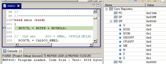
That is, SR shows
SCG1 0
SCG0 1
OSCOFF 0
CPUOFF 0
This is not any low power mode. And the firmware seems to work fine.
I read the description about DCO in section 5.25 of the user's guide. But I can't understand it well.
What happens?
Kusanagi