


Part Number: MSP430F5529
I am trying to read data from a temperature sensor over I2C. I have managed to get comms up and running however I have found some strange behavior.
I am unable to time the stop flag correctly and the result is that I read to much data.
My question is this, how do I assert the Stop flag on the second frame without the delay that I am experiencing resulting on the stop being asserted on the fourth frame?
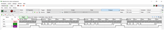
The image above demonstrates the stop flag timing issue. NOTE the DIO2 Signal is when the STP flag is asserted. I then set the DIO2 signal to zero upon the beginnings of a new I2C transaction.
to be clear I want I2C structure as follows:
| S | Address | R | A | Data | A | Data | NAK | P |
What i am getting:
| S | Address | R | A | Data | A | Data | A | Undesired Data | A | Undesired Data |NAK | P |
CODE:
#include <msp430.h>
#include <stdint.h>
unsigned char RXData;
unsigned char TXData;
uint8_t RXByteCtr = 0;
uint8_t TXByteCtr = 0;
void I2CInit(void)
{
P3REN |= 0x03;
P3OUT |= 0x03;
P3SEL |= 0x03; // Assign I2C pins to USCI_B0
UCB0CTL1 |= UCSWRST; // Enable SW reset
UCB0CTL0 = UCMST + UCMODE_3 + UCSYNC; // I2C Master, synchronous mode
UCB0CTL1 = UCSSEL_2 + UCSWRST; // Use SMCLK, keep SW reset
UCB0BR0 = 10; // fSCL = SMCLK/10 = 100kHz
UCB0BR1 = 0;
UCB0I2CSA = 0x48; // Slave Address is 048h
UCB0CTL1 &= ~UCSWRST; // Clear SW reset, resume operation
}
void I2CWriteInit(void)
{
UCB0CTL1 |= UCTR;
UCB0IFG &=~ UCTXIFG;
UCB0IE &=~ UCRXIE;
UCB0IE |= UCTXIE;
}
void I2CReadInit(void)
{
UCB0CTL1 &=~ UCTR;
UCB0IFG &=~ UCRXIFG;
UCB0IE &=~ UCTXIE;
UCB0IE |= UCRXIE;
}
void ReadTemp(void)
{
while (UCB0STAT & UCBBUSY);
P1OUT &= ~BIT6;
RXByteCtr = 2;
I2CReadInit();
UCB0CTL1 |= UCTXSTT;
}
void SetRegPtr(void)
{
while (UCB0STAT & UCBBUSY);
TXByteCtr = 1;
TXData = 0x00;
I2CWriteInit();
UCB0CTL1 |= UCTXSTT;
}
int main(void)
{
WDTCTL = WDTPW + WDTHOLD;
I2CInit();
P1DIR |= BIT6;
P1OUT &= ~BIT6;
__enable_interrupt();
SetRegPtr();
while(1)
{
ReadTemp();
}
}
#pragma vector = USCI_B0_VECTOR
__interrupt void USCI_B0_ISR(void)
{
switch(__even_in_range(UCB0IV,12))
{
case 10:
if (RXByteCtr--)
{
RXData = UCB0RXBUF;
}
else
{
UCB0CTL1 |= UCTXSTP;
P1OUT |= BIT6;
}
break;
case 12:
if (TXByteCtr)
{
UCB0TXBUF = TXData;
TXByteCtr--;
}
else
{
UCB0CTL1 |= UCTXSTP;
UCB0IFG &= ~UCTXIFG;
}
break;
default: break;
}
}

