


Part Number: MSP430F5529
Hello All (again), I am working on a simple project where
- I am using the 12bit ADC inside MSP430F5529 to measure temperature.
- ADC result is transferred to RAM by DMA0 (trigger by ADC12IFGx). Once DMA0 transfer finishes, its ISR calculate temperature based on some internal calibration parameters.
- Temperature in ºC (AB.CD↵ => 6 bytes) is transfer to UART by DMA1 (software trigger by setting DMAREQ bit).
ADC is producing 1 sample every second and UART is running at 115,200 b/s..
Following is my code:
#include <msp430f5529.h>
#include <stdint.h>
#include <stdio.h>
#include <float.h>

#define ADC_RESULTION_BITS 12
unsigned DMA_DST;                                                       // Global variables
unsigned int CAL_ADC_T30;
unsigned int CAL_ADC_T85;
unsigned int i =0;
char string [6];

float temperature;

void IO_config (void)
// configure IOs
{
        P1DIR |= 0x01;                                                   // configure P1.0 as output (RED LED)
        P4DIR |= 0x80;                                                   // configure P4.7 as output (GREEN LED)
        P1OUT |= 0x00;                                                   // initialize LED to off
        P4OUT |= 0x00;                                                   // initialize LED to off
        P4SEL |= BIT4 + BIT5;                                            // Port Configuration for UART
}

void DMA_config (void)
// configure DMA
{
// Setup DMA0
        DMACTL0 = DMA0TSEL_24;                                           // ADC12IFGx triggered
        DMACTL4 = DMARMWDIS;                                             // Read-modify-write disable
        DMA0CTL &= ~DMAIFG;                                              // Enable DMA interrupt
        DMA0CTL = DMADT_4+DMAIE;                                         // Repeated Single Transfer + Increment source address + Enable DMA Interrupt + DST/SRC both Word
        DMA0SZ = 1;                                                      // Block size
        __data20_write_long((uintptr_t) &DMA0SA,(uintptr_t) &ADC12MEM0); // Source single address
        __data20_write_long((uintptr_t) &DMA0DA,(uintptr_t) &DMA_DST);   // Destination single address
        DMA0CTL |= DMAEN;                                                // Enable DMA0, pending trigger from ADC

// Setup DMA1
        DMACTL0 |= DMA1TSEL_0;                                           // Software Controls DMA1
        DMA1CTL = DMADT_4+DMASRCBYTE+DMADSTBYTE;                         // Repeated Single Transfer + Enable DMA Interrupt + Enable DMA Interrupt + DST/SRC both byte
        DMA1SZ = 1;                                                      // Block size
        __data20_write_long((uintptr_t) &DMA1SA,(uintptr_t) &string[0]); // Initialize Source single address
        __data20_write_long((uintptr_t) &DMA1DA,(uintptr_t) &UCA1TXBUF); // Initialize Destination single address
        DMA1CTL |= DMAEN;                                                // Enable DMA1, pending SW trigger
}

void ADC_config()
{
// ADC Core control
        ADC12CTL0  |= ADC12SHT00 + ADC12SHT01 + ADC12SHT02 + ADC12SHT03;
        ADC12CTL0  |= ADC12SHT10 + ADC12SHT11 + ADC12SHT12 + ADC12SHT13; // Sample-and-hold time set to 1024 ADC12CLK cycle
        REFCTL0    |= (REFMSTR + REFON + REFVSEL_3);                     // Reference voltage 2.5V
        ADC12CTL1  |= ADC12SHP;                                          // S/H signal comes from Sample Timer
        ADC12CTL1  |= ADC12SSEL0;                                        // Set ADC12 clock source to ACLK (32,768kHz)
        ADC12CTL1  |= ADC12DIV0 + ADC12DIV1 + ADC12DIV2;                 // Set ADC12 divider to 8
        ADC12MCTL0 |= 0x0A;                                              // Configure 12-bit ADC0 control register to 0x0A (1010b) for temperature diode
        ADC12MCTL0 |= ADC12SREF0;                                        // Select reference voltage (VREF+ and VR- = AVSS)
        ADC12CTL2  |= ADC12PDIV;                                         // Set ADC12 pre-divider to 4
                                                                         // Based on ACLK at 32,768Hz, divider = 8 and pre-divider = 4, therefore ADCLK is 1,024kHz
                                                                         // sample-hold at 1024 clock circle, so ADC will output 1 reading every second
        ADC12CTL2  |= ADC12RES_2;                                        // 12-bit resolution
        ADC12CTL0  |= ADC12ON;                                           // ADC12 Turn ON
        ADC12CTL0  |= ADC12ENC;                                          // Enable ADC
}

void ConfigUCS (void)
//Configure SMCLK to 4MHz
{
        P5SEL |= BIT2 | BIT3;                                            // Configure IO as XT2 function
        UCSCTL6 &= ~XT2OFF;                                              // Enable XT2
        UCSCTL4 |= SELA_2;                                               // first configure ACLK source as REFCLK
        UCSCTL3 |= SELREF_2;                                             // Configure FLLCLK source as REFCLK

        while (SFRIFG1 & OFIFG) {
            UCSCTL7 &= ~(XT2OFFG + XT1LFOFFG + DCOFFG);                  // Clear the three types of clock flags
                                                                         // There are three flag bits that need to be cleared because any
                                                                         // The flag bit will set OFIFG
            SFRIFG1 &= ~OFIFG;                                           // Clear clock error flag
        }
        UCSCTL4 = UCSCTL4 & (~(SELS_7 | SELM_7)) | SELS_5 | SELM_5;      // Configure SMCLK and MCLK clock sources as XT2
}

void ConfigUART (void)
// Configure UART to 115kbps
{
        P4SEL |= BIT5+BIT4;                                               // Port Configuration
        UCA1CTL1 |= UCSWRST;                                              // Software reset of UCA1 module
                                                                          // Initialize control register UCA1XTL0.
                                                                          // Default is: no Parity / LSB first / 8bit / One stop bit / UART / Asynchrnoous mode
        UCA1CTL1 |= UCSSEL_2;                                             // Set SMCLK (SMCLK is at 4MHz) to BRCLK.
        UCA1MCTL |= UCOS16;                                               // Oversampling mode
                                                                          // N = 4,000,000/115,200 = 34.722
        UCA1BR0 |= 0x02;                                                  // UCBR0 = INT (N/16) = 2
        UCA1MCTL|= UCBRF1;                                                // UCBRF1 = 2
        UCA1MCTL|= UCBRS_1 + UCBRF_0;
        UCA1CTL1&= ~UCSWRST;                                              // **Initialize USCI state machine**
        i = 0;

}

int main(void)
{
        WDTCTL = WDTPW + WDTHOLD;                                         // Stop WDT
        IO_config();
        ConfigUCS ();
        ConfigUART();
        DMA_config();
        ADC_config();

        unsigned int* p = (unsigned int *)0x001A22;                        // Address of
        CAL_ADC_T30 = p[0];                                                // Temperature Calibration at 30C
        CAL_ADC_T85 = p[1];                                                // Temperature Calibration at 85C
        __bis_SR_register(GIE);

        while (1)
        {
            ADC12CTL0|= ADC12SC;                                           // Start ADC12 conversion
            // Once ADC12 conversion finishes, following will happen:
            // Its interrupt flag ADC12IFGx will trigger DMA0 to transfer conversion result from ADC12MEM0
            // to variable DMA_DST
            // Once the DMA operation finishes, DMA ISR will calculate temperature and store the result
            // in string[0]..string[5] as ASCII code
        }
}

//------------------------------------------------------------------------------
// DMA Interrupt Service Routine
//------------------------------------------------------------------------------
#pragma vector=DMA_VECTOR
__interrupt void DMA_ISR(void)
{
    switch(__even_in_range(DMAIV,16))
    {
        case 0: break;
        case 2:                                                                   // When DMA finishes transfer the data
            {
                ADC12CTL0|= !ADC12SC;                                             // Stop ADC conversion
                P1OUT ^= BIT0;                                                    // Blink the LEDs
                P4OUT ^= BIT7;
                temperature = (float)((float)DMA_DST - CAL_ADC_T30)*(85-30)/(CAL_ADC_T85 - CAL_ADC_T30)+30; // Calculate temperature reading
                sprintf (string, "%.2f", temperature);
                string[5] = 0x0d;                                                  // Add Carriage Return to the last character to sent
                UCA1IE  |= UCTXIE;                                                 // Enable Interrupt for the UART controller
                UCA1IFG |= 0x02;                                                   // Manually set the TxIFG
                i = 0;
                break;
            }
        case 4: break;                                                             // DMA1IFG = DMA Channel 1
        case 6: break;                                                             // DMA2IFG = DMA Channel 2
        case 8: break;                                                             // DMA3IFG = DMA Channel 3
        case 10: break;                                                            // DMA4IFG = DMA Channel 4
        case 12: break;                                                            // DMA5IFG = DMA Channel 5
        case 14: break;                                                            // DMA6IFG = DMA Channel 6
        case 16: break;                                                            // DMA7IFG = DMA Channel 7
        default: break;
  }
}

#pragma vector=USCI_A1_VECTOR
__interrupt void USCI_A1_ISR(void)
{
        switch(__even_in_range(UCA1IV,4))
        {
            case 0:break;                                                   // Vector 0 - no interrupt
            case 2:break;                                                   // Vector 2 - RXIFG
            case 4:                                                         // Vector 4 - TXIFG is set
            {
                if (i<=5)
                {
                    __data20_write_long((uintptr_t) &DMA1SA,(uintptr_t) &string[i]); // Source single address
                    DMA1CTL |= DMAREQ;
                    if (i==5)
                    {
                        i=0;
                        __data20_write_long((uintptr_t) &DMA1SA,(uintptr_t) &string[i]); // Source single address
                        UCA1IE  = 0x00;
                        break;
                    }
                    else
                    {
                        i++;
                    }
                }                                                                                     // Vector 4 - TXIFG
            }
            default: break;
        }
}
I am a newbie in c-programming, so I am fully aware that this code has done many not-recommended thing (e.g. doing floating point calculation in an ISR).
However, my immediate problem is that when I step through the code, the first character of the first ADC reading is transmitted twice by the DMA1 to UART. Therefore, UART will write i.e. AAB.CD↵.
For example, first execute this code, i = 0, the DMA1 source address is configured to be 0x2400 (where x[0] is stored)
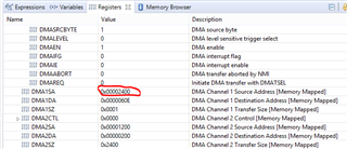

Once the DMA1 triggered, first character "2" is transmitted

continue stepping through the code, i is incremented to 1, now the DMA1 source address is updated to 0x2401 (where x[1] is stored)

however, after trigger, UCA1TXBUF didn't update, so character "2" was sent again


continue stepping through the code, i is incremented to 2, now the DMA1 source address is updated to 0x2402 (where x[2] is stored)

however, after trigger, UCA1TXBUF did update, so character "8" was sent
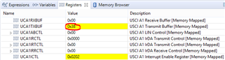
Consequential DMA operation seems fine

Maybe there's something wrong when I initialize the DMA1 for the first time?


