This thread has been locked.

If you have a related question, please click the "Ask a related question" button in the top right corner. The newly created question will be automatically linked to this question.

MSP430FR2512: Captivate startup time

Part Number: MSP430FR2512


Hi,

after successful communication with REGISTER_I2C, I have a new big problem: Startup time.

    WDTCTL = WDTPW + WDTCNTCL + WDTIS_4;
	BSP_configureMCU();
	__bis_SR_register(GIE);

This code is not working while function BSP_cofigureMCU() needs over 1 second (!) to finish.

    WDTCTL = WDTPW + WDTCNTCL + WDTIS_3;
	BSP_configureMCU();
	__bis_SR_register(GIE);

This works fine because WDT reset time is set to 16 seconds.

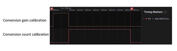
I need a Startup time below 200 ms and here is the question is this theoretically possible?

Best regards

Igor

  • Now I found new information. The main problem at startup is CS_initFLL() which takes a lot of time. I don't know why this function takes so much time. Do you have any solution to shorter this initialization? Afterward, whit I2C you don't need an accurate clock.

    Another thing is calibration, but this can be avoided with a lower conversion count.

    Best regards

    Igor

  • Hi Igor,

    Are you using a 32KHz crystal connected to the LFXT1 pins?  This is usually the culprit.  You can select the internal REFO clock instead in the BSP.c file, but keep in mind this will add 15uA of current when using REFO.

    Regarding calibration, you can't avoid that and you are correct regarding the lower conversion count = shorter calibration time.

  • No, I don't use any crystal. Code is generated with Design Center and everything works fine, just this long startup is the problem.

    How can I select REFO? Additional current is not an issue at all.

    I'm not familiar with MSP at all, this is my first project.

  • Ok, I found it. I'll try and will report my progress.

  • Hi,

    I shorted startup time to 0.8 second with lower conversion count and this is ok.

    After initial startup, I set the Conversion Count to 500 with Parameter Package (0X81).

    After that, I send Parameter 0x8E to force calibration. This calibration takes 2.6s

    I also measure startup calibration time CAPT_appStart() and this takes 1.3s for Conversion count = 500.

    Why force calibration takes twice as long as CAPT_appStart()?

    Do you have any solution for this?

    Best regards

    Igor

  • Hi Igor,

    Ok, it sounds like you got the REFO clock figured out.  For those who may come across this post in the future, the REFO clock can be selected in the CAPT_bsp.h file and looks like this:

    Now regarding the calibration time, 1.3 is actually quite long.  2.6 seconds tells me that calibration is happening twice.  But you say you are using 500 conversion count.  Something doesn't seem to add up here.

    In addition to the conversion count, the conversion frequency also has an influence on the total time.  Using a 4MHz conversion clock vs. a 1MHz will get through the calibration 4x faster.  But you have to be mindful that at higher clock frequencies, larger electrode capacitances won't have sufficient time to charge up during each clock cycle and will cause measurement inaccuracies.  What conversion frequency are you using?

    As an example here is the measurement time for the proximity sensor on the BSWP panel.  I set the target conversion count = 500.  The calibration process has 2 -steps; calibrate gain, then calibrate offset.  You can see from the measurements it takes <100ms.

    Now this is only one electrode and on devices that have 4 measurement blocks, you can calibrate up to 4 electrodes in parallel.

    You are using the FR2512, which has only 1 measurement block.  So if you have more than one electrode, each will be calibrated in sequential order.  So if it takes 100ms to calibrate one electrode, then total time will be about 400ms. 

    Out of curiosity, how are you measuring the calibration time and how many electrodes do you have?

  • Hi Dennis,

    yes, regarding REFO it is like you said.

    My starup looks like this:

    1.  Starting point right after port initialization

    2. End of BSP_configureMCU()  - start CAPT_appStart()

    Time 1-2: 0.21s

    3. End of CAPT_appStart() - now the touch board is in the main while(1)

    Conversion count 150

    Conversion gain 100

    Time 2-3: 0.56s

    4. Point where I send 0x81 parameter Conversion count 420 - normal operation is stopped

    5. Here my host MCU start reading touch buttons

    6. End of Force calibration and start normal operation

    Time 4-5: 1.27s

    Time 5-6:  1.17s - here is my problem because the host device is not operational for this time (the user must wait for the first touch)

    Time 4-6: 2.47s - total time of Force Calibration. This time is the same if I send just 0x81 or 0x8E after 0x81.

    Form point 1. MSP430 is powered constantly. Measurements are done with P1OUT BIT1 so there is no mistake.

    Here is the picture of what is happening when the user presses the touch buttons too early (before point 6) - a few presses:

    Time 6-7: 1.27s

    8. Normal operation

    Time 6-8: 6.3s - depends on how long you will press the buttons but this is normal.

    I think time 6-7 is recalibration, but here is still the question of why this recalibration is two times shorter than Force calibration?

    Thank you for your time.

    Best regards

    Igor

  • Igor,

    Can you send me copies of your CAPT_UserConfig.c and .h files?

  • Here it is:

    #include "CAPT_UserConfig.h"
    
    //*****************************************************************************
    //
    //! Captivate Element Definitions
    //! All elements in this application are defined below.
    //! Each element has 3 components:
    //!  1) a raw count array (One index per freq. scanned) (uint16_t)
    //!  2) a tuning array (One index per freq. scanned) (tCaptivateElementTuning)
    //!  3) a element structure (tElement)
    //
    //*****************************************************************************
    // Sensor: BTN00, Element: E00
    uint16_t BTN00_E00_RawCnts[CAPT_SELF_FREQ_CNT];
    tCaptivateElementTuning BTN00_E00_Tuning[CAPT_SELF_FREQ_CNT];
    tElement BTN00_E00 =
    {
        .ui8RxPin = 2,
        .ui8RxBlock = 0,
        .ui8TouchThreshold = 10,
        .pRawCount = BTN00_E00_RawCnts,
        .pTuning = BTN00_E00_Tuning,
    };
    
    // Sensor: BTN00, Element: E01
    uint16_t BTN00_E01_RawCnts[CAPT_SELF_FREQ_CNT];
    tCaptivateElementTuning BTN00_E01_Tuning[CAPT_SELF_FREQ_CNT];
    tElement BTN00_E01 =
    {
        .ui8RxPin = 3,
        .ui8RxBlock = 0,
        .ui8TouchThreshold = 10,
        .pRawCount = BTN00_E01_RawCnts,
        .pTuning = BTN00_E01_Tuning,
    };
    
    // Sensor: BTN00, Element: E02
    uint16_t BTN00_E02_RawCnts[CAPT_SELF_FREQ_CNT];
    tCaptivateElementTuning BTN00_E02_Tuning[CAPT_SELF_FREQ_CNT];
    tElement BTN00_E02 =
    {
        .ui8RxPin = 0,
        .ui8RxBlock = 0,
        .ui8TouchThreshold = 10,
        .pRawCount = BTN00_E02_RawCnts,
        .pTuning = BTN00_E02_Tuning,
    };
    
    // Sensor: BTN00, Element: E03
    uint16_t BTN00_E03_RawCnts[CAPT_SELF_FREQ_CNT];
    tCaptivateElementTuning BTN00_E03_Tuning[CAPT_SELF_FREQ_CNT];
    tElement BTN00_E03 =
    {
        .ui8RxPin = 1,
        .ui8RxBlock = 0,
        .ui8TouchThreshold = 10,
        .pRawCount = BTN00_E03_RawCnts,
        .pTuning = BTN00_E03_Tuning,
    };
    
    
    //*****************************************************************************
    //
    //! Captivate Time Cycle Definitions
    //! All time cycles in this application are defined below.  Time cycles are
    //! groups of elements that are measured together in parallel in one time slot.
    //! Each cycle has 2 components:
    //!  1) an element pointer array to the member elements (tElement*)
    //!  2) a cycle structure (tCycle)
    //
    //*****************************************************************************
    // Time Cycle: BTN00_C00
    tElement* BTN00_C00_Elements[1] =
    {
        &BTN00_E00,
    };
    tCycle BTN00_C00 =
    {
        .ui8NrOfElements = 1,
        .pElements = BTN00_C00_Elements,
    };
    
    // Time Cycle: BTN00_C01
    tElement* BTN00_C01_Elements[1] =
    {
        &BTN00_E01,
    };
    tCycle BTN00_C01 =
    {
        .ui8NrOfElements = 1,
        .pElements = BTN00_C01_Elements,
    };
    
    // Time Cycle: BTN00_C02
    tElement* BTN00_C02_Elements[1] =
    {
        &BTN00_E02,
    };
    tCycle BTN00_C02 =
    {
        .ui8NrOfElements = 1,
        .pElements = BTN00_C02_Elements,
    };
    
    // Time Cycle: BTN00_C03
    tElement* BTN00_C03_Elements[1] =
    {
        &BTN00_E03,
    };
    tCycle BTN00_C03 =
    {
        .ui8NrOfElements = 1,
        .pElements = BTN00_C03_Elements,
    };
    
    
    //*****************************************************************************
    //
    //! Captivate Sensor Definitions
    //! All sensors in this application are defined below.  Sensors are
    //! groups of time cycles that utilize raw measurement data to create an
    //! abstract sensor type, such as a button, slider, wheel, or prox sensor.
    //! Each sensor has 3 components:
    //!  1) a cycle pointer array to the member time cycles (tCycle*)
    //!  2) a sensor-specific parameter structure (tGenericSensorParams)
    //!  3) a sensor structure (tSensor)
    //
    //*****************************************************************************
    //Sensor: BTN00
    const tCycle* BTN00_Cycles[4] =
    {
        &BTN00_C00,
        &BTN00_C01,
        &BTN00_C02,
        &BTN00_C03,
    };
    
    tButtonSensorParams BTN00_Params;
    tSensor BTN00 =
    {
        // Basic Properties
        .TypeOfSensor = eButtonGroup,
        .SensingMethod = eSelf,
        .DirectionOfInterest = eDOIDown,
        .pvCallback = NULL,
        .ui8NrOfCycles = 4,
        .pCycle = BTN00_Cycles,
        .pSensorParams = (tGenericSensorParams*)&BTN00_Params,
        // Conversion Control Parameters
        .ui16ConversionCount = 150,
        .ui16ConversionGain = 100,
        .ui8FreqDiv = 2,
        .ui8ChargeLength = 0,
        .ui8TransferLength = 0,
        .bModEnable = false,
        .ui8BiasControl = 3,
        .bCsDischarge = true,
        .bLpmControl = false,
        .ui8InputSyncControl = 0,
        .bTimerSyncControl = false,
        .bIdleState = true,
        // Tuning  Parameters
        .ui16ProxThreshold = 10,
        .ui16NegativeTouchThreshold = 30,
        .ui16ErrorThreshold = 8191,
        .ui16TimeoutThreshold = 65535,
        .ProxDbThreshold.DbIn = 1,
        .ProxDbThreshold.DbOut = 0,
        .TouchDbThreshold.DbIn = 1,
        .TouchDbThreshold.DbOut = 0,
        .bCountFilterEnable = true,
        .ui8CntBeta = 1,
        .bSensorHalt = false,
        .bPTSensorHalt = true,
        .bPTElementHalt = true,
        .ui8LTABeta = 7,
        .bReCalibrateEnable = true,
    };
    
    
    #if (CAPT_CONDUCTED_NOISE_IMMUNITY_ENABLE==true)
    //*****************************************************************************
    //
    //! \var g_EMCConfig
    //! This structure stores the EMC configuration for this application.
    //
    //*****************************************************************************
    const tEMCConfig g_EMCConfig =
    {
    	// Conversion Style
    	.selfModeConversionStyle = CAPT_SELF_MODE_CONVERSION_STYLE,
    	.projModeConversionStyle = CAPT_PROJ_MODE_CONVERSION_STYLE,
    	
    	// Oversampling Style
    	.selfModeOversamplingStyle = CAPT_SELF_MODE_OVERSAMPLING_STYLE,
    	.projModeOversamplingStyle = CAPT_PROJ_MODE_OVERSAMPLING_STYLE,
    	
    	// Jitter Filter Enable
    	.bJitterFilterEnable = true,
    	
    	// Noise Thresholds and Calibration Noise Limits
    	.ui8NoiseThreshold = CAPT_NOISE_THRESHOLD,
    	.ui16CalibrationNoiseLimit = CAPT_CALIBRATION_NOISE_LIMIT,
    	.ui8CalibrationTestSampleSize = 8,
    		
    	// Dynamic Threshold Adjustment Parameters
    	.bEnableDynamicThresholdAdjustment = CAPT_DYNAMIC_THRESHOLD_ADJUSTMENT,
    	.ui8MaxRelThreshAdj = 76,
    	.ui8NoiseLevelFilterEntryThresh = 40,
    	.ui8NoiseLevelFilterExitThresh = 0,
    	.ui8NoiseLevelFilterDown = 6,
    	.ui8NoiseLevelFilterUp = 1,
    	.coeffA = _IQ31(0.0065),
    	.coeffB = _IQ31(0.050)
    };
    #endif
    
    //*****************************************************************************
    //
    //! \var g_pCaptivateSensorArray
    //! This array allows for indexed access to any
    //! sensor in the configuration.
    //
    //*****************************************************************************
    tSensor* g_pCaptivateSensorArray[CAPT_SENSOR_COUNT] =
    {
        &BTN00,
    };
    
    
    //*****************************************************************************
    //
    //! \var g_uiApp
    //! This structure stores the global settings for this application.
    //
    //*****************************************************************************
    tCaptivateApplication g_uiApp =
    {
        .state = eUIActive,
    	.pSensorList = &g_pCaptivateSensorArray[0],
        .ui8NrOfSensors = CAPT_SENSOR_COUNT,
        .ui8AppLPM = CAPT_LOW_POWER_MODE,
        .bElementDataTxEnable = true,
        .bSensorDataTxEnable = true,
        .ui16ActiveModeScanPeriod = 10,
        .ui16WakeOnProxModeScanPeriod = 100,
        .ui16InactivityTimeout = 32,
        .ui8WakeupInterval = 5,
    };
    

    #ifndef CAPT_USERCONFIG_H_
    #define CAPT_USERCONFIG_H_
    
    //
    // CapTIvate User Configuration Template Version
    //
    #ifndef __CAPTIVATE_CONFIG_VERSION__
    #define __CAPTIVATE_CONFIG_VERSION__ 18300
    #endif
    
    //
    // Include the CapTIvate Software Library
    //
    #include "captivate.h"
    
    //
    // Compile-Time System Configuration Definitions
    //
    #define CAPT_SENSOR_COUNT                     (1)
    #define CAPT_INTERFACE  (__CAPT_REGISTERI2C_INTERFACE__)
    #define CAPT_WAKEONPROX_ENABLE  (false)
    #define CAPT_WAKEONPROX_SENSOR  (none)
    #define CAPT_TRACKPAD_ENABLE  (false)
    #define CAPT_LOW_POWER_MODE (LPM0_bits)
    
    //
    // Compile-Time Noise Immunity Configuration Definitions
    //
    #define CAPT_CONDUCTED_NOISE_IMMUNITY_ENABLE  (true)
    #define CAPT_SELF_MODE_CONVERSION_STYLE  (eMultiFrequency)
    #define CAPT_PROJ_MODE_CONVERSION_STYLE  (eMultiFrequencyWithOutlierRemoval)
    #define CAPT_SELF_MODE_OVERSAMPLING_STYLE  (e2xOversampling)
    #define CAPT_PROJ_MODE_OVERSAMPLING_STYLE  (eNoOversampling)
    #define CAPT_NOISE_THRESHOLD  (50)
    #define CAPT_CALIBRATION_NOISE_LIMIT  (50)
    #define CAPT_DYNAMIC_THRESHOLD_ADJUSTMENT  (true)
    
    //
    // Captivate Frequency Count Definitions
    // If conducted noise is enabled, multiple
    // frequency scanning is enabled.  These definitions
    // ensure that RAM space is set aside to store
    // frequency specific information.
    //
    #if CAPT_CONDUCTED_NOISE_IMMUNITY_ENABLE
    #define CAPT_SELF_FREQ_CNT        (4)
    #define CAPT_MUTUAL_FREQ_CNT      (4)
    #else
    #define CAPT_SELF_FREQ_CNT        (1)
    #define CAPT_MUTUAL_FREQ_CNT      (1)
    #endif
    
    //*****************************************************************************
    //
    //! \def CAPT_MS_TO_CYCLES is a macro to convert a period value in 
    //! milliseconds to an approximate cycle count based on a 
    //! 32.768 kHz clock frequency.
    //
    //*****************************************************************************
    #define CAPT_MS_TO_CYCLES(ms)                                         (ms * 32)
    
    //*****************************************************************************
    //
    //! \def CAPT_MS_TO_CYCLES_VLO is a macro to convert a period value in
    //! milliseconds to an approximate cycle count based on a
    //! 10 kHz clock frequency.  The VLO oscillator is approximately 10 kHz.
    //
    //*****************************************************************************
    #define CAPT_MS_TO_CYCLES_VLO(ms)                                     (ms * 10)
    
    //
    // Captivate Sensor Prototypes
    // These prototypes enable access to sensors
    // from the application.
    //
    extern tSensor BTN00;
    
    //*****************************************************************************
    //
    //! \var g_EMCConfig
    //! This structure stores the EMC configuration for this application.
    //
    //*****************************************************************************
    extern const tEMCConfig g_EMCConfig;
    
    //*****************************************************************************
    //
    //! \var g_pCaptivateSensorArray
    //! This array allows for indexed access to any
    //! sensor in the configuration.
    //
    //*****************************************************************************
    extern tSensor* g_pCaptivateSensorArray[CAPT_SENSOR_COUNT];
    
    //*****************************************************************************
    //
    //! \var g_uiApp
    //! This structure stores the global settings for this application.
    //
    //*****************************************************************************
    extern tCaptivateApplication g_uiApp;
    
    //*****************************************************************************
    //
    //! Software Library / User Configuration Version Check
    //
    //*****************************************************************************
    #ifndef __CAPTIVATE_LIB_VERSION__
    #warning "CapTIvate library version not found by user configuration."
    #elif __CAPTIVATE_LIB_VERSION__ != __CAPTIVATE_CONFIG_VERSION__
    #warning "CapTIvate software library and user configuration version mismatch."
    #endif
    
    #endif /* CAPT_USERCONFIG_H_ */


  • Hi Dennis,

    I found where is the problem.

    After the first start-up (power on) of MSP430, command 0x81 takes two times than normal.

    I added a short pulse on P1OUT BIT1 to catch calibration start:

    void CAPT_calibrateUI(tCaptivateApplication *pApp)
    {
        uint8_t ui8SensorID;
    
        //
        // Loop through all of the sensors in the application pointed to by
        // pApp.  For each sensor, call the appropriate calibration routine via
        // the calibration macro.
        //
        if(P1OUT & BIT1)
        {
            P1OUT &= ~BIT1;
            P1OUT |= BIT1;
        }
        else
        {
            P1OUT |= BIT1;
            P1OUT &= ~BIT1;
        }
        for (ui8SensorID=0; ui8SensorID<pApp->ui8NrOfSensors; ui8SensorID++)
        {
            CAPT_MANAGER_CALIBRATE_SENSOR(pApp->pSensorList[ui8SensorID]);
        }
    }
    

    Here is the picture when a normal power-up happened:

    1. Power up

    2. Here I send 0x81

    3. Point where calibration actually starts (short pulse on P1OUT)

    Time 2-3: 1.25s

    Time 3-4: 1.25s

    Channels below are SCL and SDA lines of the host MCU.

    Point 2 more precisely:

    Here is the picture when host MCU is restarted with reset command, MSP430 stay powered:

    1. Restart host MCU

    2. Send 0x81

    3. Calibration start

    Point 2 and 3 more precisely:

    Time 2-3: 10ms

    So, after power-on and very the first 0x81 command MSP430 goes somewhere (I can't debug this) for 1.25s, but for sure not to calibration.

    Do you have any solution for this? Right now I'm a little bit in hurry...

    Best regards

    Igor

  • Hi Igor,

    I'm looking through the source code now to see what is causing the first delay.  I'm also setting up HW to see if I can duplicate.  I see you are short on time so I will do my best to get a solution quickly.

    I also have an alternative calibration routine that will cut calibration time by 1/3.  The default calibration routine uses a linear search to go through all the gain and offset settings during calibration.  This alternative routine uses a binary search tree so the time is cut dramatically.  We are in the process of releasing this alternative calibration in our next Captivate release, but I will provide to you now.  I will prepare it with instructions on how to implement.

  • Hi Igor,

    I using FR2633 EVM and FR2433 Launchpad as the host.  I want to point out that I have the FR2633 configured to be one sensor with 4 elements where each element is in it's own measurement cycle.  This would be the same as the FR2512, 4 elements, 4 measurement cycles.  Because of this, when a calibration is performed, it is done one cycle at a time, so again for the FR2512 it would take 4 calibration cycles. I'm using 150 for the conversion count with f/4 conversion clock (4MHz).  The effective conversion rate is 2MHz because one clock cycle for charge, the second clock cycle for transfer.

    I can get the host to send 0x8E.  In this picture ch2 trace is the calibration being performed (112ms for the 4 cycles).  The ch3 trace is the slave checking for inbound packet in the app_handler where I toggle an IO pin.   Ch 4,5 are I2C.  As you can see there is only calibration per request.  The first calibration on the left is my first request for calibration after device reset.

    Here a zoom in showing the relationship between when the 0x8E command is received, then checked for inbound packet, and calibrated.  Notice the command is asynchronous to when the slave is checking for inbound packets, but on the next check it processes the command and performs the calibration.  I only see one calibration per command from the host.

    And here is the I2C message.

    I'm still working on getting the quicker calibration routine for you.

    Do you by chance have an oscilloscope or does your logic analyzer have analog channels?  I ask because I may have you probe each of the four Captivate channels and measure the actual time the electrodes are performing the charge/transfers.

  • Hi Dennis,

    thank you for your effort.

    After changing the conversion count to 700 I found out that this death time is the same as calibration time. The only  explanation is, that calibration is started twice, but the first time the entry point is not in:

    void CAPT_calibrateUI(tCaptivateApplication *pApp)
    

    So I do a simpy workaround with one global variable put in main:

    	CAPT_appStart();
        first_startup = 1;


    and check it in void CAPT_calibrateUI(tCaptivateApplication *pApp):

        if(first_startup == 1)
        {
            first_startup = 0;
        }
        else
        {
            for (ui8SensorID=0; ui8SensorID<pApp->ui8NrOfSensors; ui8SensorID++)
            {
                CAPT_MANAGER_CALIBRATE_SENSOR(pApp->pSensorList[ui8SensorID]);
            }
        }
    

    After that, the result is:

    1. Power up

    2. 0x81 parameter

    3. Normal operation which is only 20ms after host MCU shows screen but this is not an issue.

    Time 2-3: 1.35s with conversion count 500.

    After reading the 0x81 parameter MSP43 board has a conversion counter set to 500.

    So, the problem is solved, but a shorter startup would be very welcome to reach an even shorter calibration time on power-up. I will wait for a new version.

    Thank you very much and best regards.

    Igor

  • Hi Igor,

    Attached is the CCS project that demonstrates and compares the default calibration to the faster BST (binary search tree).  The two files you need for your project are CAPT_calibration_BST.c and .h.  Just copy them over.  Also in the zip file is a pdf describing the changes you need to make to your project.  Let me know how it works for you.

    FR2633_BST_calibration_demo.zip

  • Hi Dennis,

    this new function for calibration is much faster but did not solve the problem. After the calibration, the program jumps into CAPT_updateUI() and make another calibration here:

            if ((MAP_CAPT_testForMaxCountRecalibration(pApp->pSensorList[ui8SensorID]) == true) ||\
                (MAP_CAPT_testForNegativeTouchRecalibration(pApp->pSensorList[ui8SensorID]) == true) ||\
                (MAP_CAPT_testForRecalibration(pApp->pSensorList[ui8SensorID]) == true))
            {
                CAPT_MANAGER_CALIBRATE_SENSOR(pApp->pSensorList[ui8SensorID]);
    //            CAPT_calibrateSensorSA(pApp->pSensorList[ui8SensorID],false);
            }
    

    If I put a new function here, then nothing works, the program goes here constantly.

  • Hi Igor,

    To help isolate the problem, disable the automatic re-calibration by setting the sensors' structure member .bReCalibrateEnable = false.  If you do this, you should only see the initial calibration at POR.

    Next you need to determine which of those three functions that check for recalibration shown above are returning 'true'.  Easy way is to modify the if() statement so only one function is called.  Then try each of the three functions to determine which one is throwing the flag.  Once you determine which function it is, we can focus on the cause.

    MAP_CAPT_testForMaxCountCalibration checks if any of the channels exceed their max count limit.  This is 8191 by default.  If you haven't changed this parameter then this would indicate something faulty with the channel or sensor element.  the sensor structure element is .ui16ErrorThreshold.  Check this is set to 8191

    MAP_CAPT_testForNegativeTouchCalibration checks if the measurement counts are reversed from the DOI, direction of interest.  For self cap mode, adding capacitance causes the count value to go lower.  If instead the measurements go higher and cross the negative touch threshold, it will be detected as a negative touch and set the flag for re-calibration.  The sensor structure element is .ui16NegativeTouchThreshold.  Check you have this set to 30.

    MAP_CAPT_testForRecalibration checks to see if the LTA has drifted by +/- 12.5% from its last calibration.  Not likely in this case.

  • Hi Dennis,

    Calibration with a new function takes about 40ms and this is excellent, but...

    I tested and MAP_CAPT_testForRecalibration(pApp->pSensorList[ui8SensorID]) returning true constantly if I call your new function.

    Do you have any idea why?

  • Hi Igor, this is strange.

    The first calibration done in CAPT_AppStart() at POR is good enough to get started, so for now if you comment out those three checks for recalibration in CAPT_manager.c, can you send data to the GUI?  If you open the sensor's 'bar view' do you see any bars?  Without touching, what level or count values do you see the blue outline bar?  And if you touch an electrode, what value does the bar change to?

  • Hi Igor,

    It's been a few days since I have heard from you so I’m assuming you were able to resolve your issue.
    If this isn’t the case, please click the "This did NOT resolve my issue" button and reply to this thread with more information.
    If this thread locks, please click the "Ask a related question" button and in the new thread describe the current status of your issue and any additional details you may have to assist us in helping to solve your issues.

**Attention** This is a public forum