Part Number: MSP430FR6047
Hi
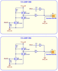
I'm going to construct it like the following circuit for amplification.
Is there anything to be careful about when organizing a circuit?
Thanks
Original question:

MSP430FR6047: External amplifier for ultrasonic flow measurement.
Part Number: MSP430FR6047
Hi
I'm going to construct it like the following circuit for amplification.
Is there anything to be careful about when organizing a circuit?
Thanks
**Attention** This is a public forum