This thread has been locked.

If you have a related question, please click the "Ask a related question" button in the top right corner. The newly created question will be automatically linked to this question.

Photodiode pulse detect system

Other Parts Discussed in Thread: TDC7201, OPA858, TLV3501

Hi, 

We have a laser signal detection system as shown in the figure below. In this system, we want to detect the incoming laser pulse. The MCU will detect the incoming pulse and perform its operations accordingly. That is, the pulse signal is either present or not. I will not take any operation with the time of flight.
The pulse signal is 10ns and ranges from 50-100MHz. An example pulse signal is seen in Figure 2.
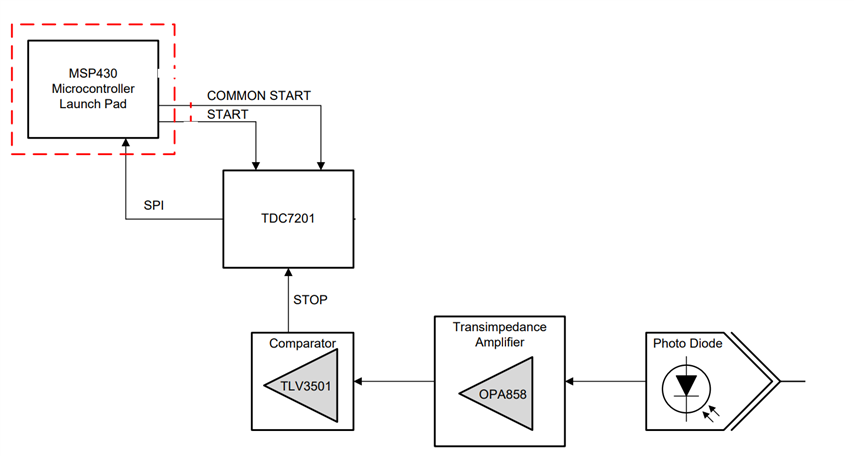
                                                                           Figure 1. Detect System 


                                                                     Figure 2. Pulse 

1) I want to detect the incoming pulse signal only with the comparator and read it with the MCU. It's a high frequency signal and I think high MCU speeds would be needed to detect it. Am i wrong? Can I miss pulse signals when I do it this way?
2) When I do it with TDC7201, can I read every incoming pulse signal from interrupt registers?

  • Hello Burak,

      1) Are you saying you want to bypass the TIA? You would need a way to convert the current input source to a voltage which is best done by an amplifier configured in a transimpedance manner. Not sure about the detection speed for the MCU, I will move this thread to our MCU team after working out the details of the TIA stage. But if you are not using the functionality of the MCU, you could improve performance by using high speed ADCs at the output of the TIA (OPA858) such as done in these reference designs: TIDA-00725 and TIDA-01187.

      2) Are you not using the Time-to-Digital Converter for time of flight measurement? Do you then need a conditional signal provided by the comparator TLV3501? 

      I can help on the TIA stage, and after solidifying the details/design, I can move this thread over to the next stage of your application. The bandwidth range is 50-100MHz, so the pulse signal has a rise time of around 3.5ns to 7ns. A few more additional questions:

    1. What is the input current range or the output range of the amplifier needed? (In other words: gain of this stage, value of the transimpedance resistance)
    2. Photodiode input capacitance 
    3. Supply range of the amplifier

    Thank you,
    Sima 

  • 1) The TIA will be at the entrance of the circuit. That part will not change. In MCU input, there are 2 options to read the signal pulse. The first is to use a comparator. Second, to use TDC7201 after comparator(Figure 1). 

    2) I just want to read whether the output is 1 or 0. I can do this with the comparator. But can I catch every incoming pulse signal? I do not know. Right here I want to know the effect of the MCU speed and the speed of the MCU timer unit on this. If I can detect these signals with the MCU at the right moments, I will not use the TDC7201.
    I was thinking of using TDC7201 for fast detection without depending on MCU speed. So I don't care about flight time. I just want the pulse signal to be detected as soon as it arrives.

    I don't need support at the TIA stage right now. Thank you.

  • Hello Burak,

      1) Understood, thank you for the clarification. The high speed TIA and comparator shouldn't be an issue with these rise/fall time speeds. 

      2) Correct, the comparator will give you this conditioned signal (high or low output). You could bypass the TDC since this will measure the time delay, a functionality you do not need. I will move the thread to MCU team. In the meantime during transition, what is the maximum pulse repetition frequency? You might need to use a high speed ADC for this application. 

    Thank you,

    Sima 

  • Hello Sima,

    Waiting for your feedback from the MCU team.

    We do not currently know the pulse repetition frequency. Pulse signals not come at regular intervals. This is how we know it now. I will inquire again and provide feedback. I'll let you know when I find out exactly that.

    Thank you,

    Burak

  • Hi Sima, 

    Our maximum pulse repetition frequency is unknown. But here I expect you to answer my question based on the 100Mhz signal.

  • Hi Burak, 

    I think you are looking for something like the Enhanced Capture Module (eCAP) that is included in Sitara MCU devices. See the AM243x family here: https://www.ti.com/product/AM2434 

    eCAP is a dedicated module for capturing pulses like you are describing coming off of the TLV3501 comparator. See the AM243x Technical Reference Manual (www.ti.com/.../spruim2c.pdf) for more information and example peripheral configurations.

    I am trying to confirm exactly what the shortest pulse period is though. This will be a combination of the eCAP clocking and the LVCMOS I/O bandwidth. The LVCMOS I/O on these devices are usually good up to 200 MHz BW or so. The eCAP peripheral on AM243x devices is clocked at MAIN_SYSCLK/4 or 125 MHz. I believe that will give you a 1/125MHz = 8ns timestamp resolution on captures. The TLV3501 in your block diagram has a maximum toggle frequency of 80 MHz. eCAP will be beyond that, so I think the TLV3501 may be your limiting device. 

    Other MCU from Sitara, and C2000 line of produces integrate eCAP, but for minimal pulse period, you will want to use MCU in the AM2x series as these provide the fastest capture rates.

    Does that answer your question?

    Thank you,

    -Randy

**Attention** This is a public forum