This thread has been locked.

If you have a related question, please click the "Ask a related question" button in the top right corner. The newly created question will be automatically linked to this question.

MSP430FR2353: MSP430 Bootloader - BSL User configurations

Part Number: MSP430FR2353


I am developing the MSP430FR2353 firmware update from another MPU over I2C bus using MSP430 BSL.

For the same, I want to make BSL user configuration specifically to change I2C communication from the default I2C bus eUSCI_B0 (pins P1.2 & P1.3) to eUSCI_B1 (pins P4.6 & P4.7).

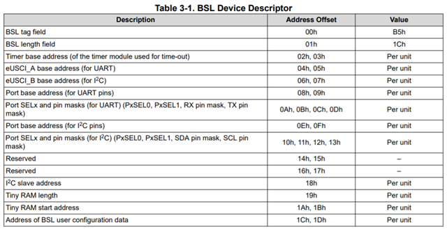
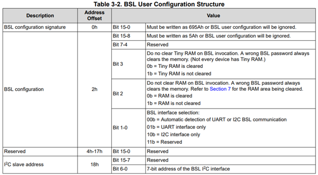
I am referring to the slau550aa.pdf. It provides two tables - "Table 3-1. BSL Device Descriptor" and "Table 3-2. BSL User Configuration Structure".

However, it seems the "Table 3-1" details does not fit into the "Table 3-2" Structure as per the required bytes.

Could anyone please help me how I can map these two tables details to get the correct BSL user configurations?

Will BSL signature and config field will replace the BSL tag/length and timer base address field or what?

BSL Device descriptor BSL User config structure

  • Hi For 3-1 is the data located at ROM that is the the default configuration of the BSL. For the 3-2 is the information can be re-configured by user it is located at FRAM.

  • Thanks for the response Gary.

    Could you please confirm my understanding on the same?

    1. Offset 0x0,0x1,0x3 must be set as 0x5a, 0x69, 0x5a respectively to enable the user config. 
    2. Offset 0x2 will be as per requirement.
    3. From offset 0x4 to 0x18, we can set as required as per the table 3.1 parameters. 
  • Yes, you are right.

  • Thanks for the confirmation Gary.

    Also do we need to add the "Address of BSL user configuration data" parameter at 0x1c and 0x1d offset? (As per table 3.1) ?

    I want to confirm because, “3.6.1.1 Example of BSL User Configuration” does not showcase that information in sample example. 

    Also, if I calculate the actual location of “BSL user configuration data”, then it will be 0xFFA4 [ 0xFF88 (base address) + 0x1C (offset) ]. That overwrites the other important addresses of the linker file. Please check the below attached screenshot.  Here, I have added BSL config (0 to 10) parameters to fill up the details as per Table 3.1. Now if I want to add 0x1c and 0x1d offset parameters, then it will overwrites the INT00 and INT01 address locations.

  • Hi Akash

    Sorry for the late response. for the BSL user configuration data is located at below

**Attention** This is a public forum