


Other Parts Discussed in Thread: MSP430F5529
Dear all,
I use MSP430F5529 to set ADC, like below:
#include <adc12_a.h>
void MSP_EXP430F5529LP_initADC(void)
{
/* Initialize PILOT ADC pin driver */
GPIO_setAsPeripheralModuleFunctionInputPin(GPIO_PORT_P6, GPIO_PIN4);
/* Initialize the ADC12_A Module */
ADC12_A_init(ADC12_A_BASE,
ADC12_A_SAMPLEHOLDSOURCE_SC,
ADC12_A_CLOCKSOURCE_ADC12OSC,
ADC12_A_CLOCKDIVIDER_1);
ADC12_A_setupSamplingTimer(ADC12_A_BASE,
ADC12_A_CYCLEHOLD_96_CYCLES,
ADC12_A_CYCLEHOLD_4_CYCLES,
ADC12_A_MULTIPLESAMPLESDISABLE);
/* Configure Memory Buffer */
ADC12_A_configureMemoryParam config_param = {0};
config_param.memoryBufferControlIndex = ADC12_A_MEMORY_0;
config_param.inputSourceSelect = ADC12_A_INPUT_A4;
config_param.positiveRefVoltageSourceSelect = ADC12_A_VREFPOS_AVCC;
config_param.negativeRefVoltageSourceSelect = ADC12_A_VREFNEG_AVSS;
config_param.endOfSequence = ADC12_A_ENDOFSEQUENCE;
ADC12_A_configureMemory(ADC12_A_BASE,
&config_param);
ADC12_A_setResolution(ADC12_A_BASE,
ADC12_A_RESOLUTION_12BIT);
ADC12_A_enable(ADC12_A_BASE);
}
I find a special waveform in ADC pin(P6.4), like below picture. Is right?
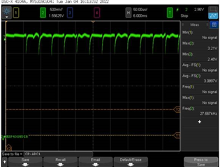
The frequency match I call readPilotADC();
uint16_t readPilotADC()
{
uint16_t measured_voltage;
ADC12_A_startConversion(ADC12_A_BASE, ADC12_A_MEMORY_0, ADC12_A_SINGLECHANNEL);
while(ADC12_A_isBusy(ADC12_A_BASE) == ADC12_A_BUSY);
measured_voltage = ADC12_A_getResults(ADC12_A_BASE, ADC12_A_MEMORY_0);
return measured_voltage;
}
I want to check this waveform is right or not?
If not, how can I solve it?
Thanks.
