Clock for MSP seems to have wrong frequency
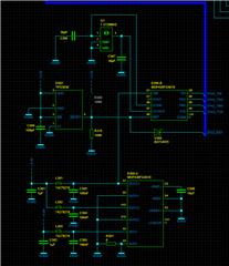
Description: On our Transmission Module we use a MSP430FG4618 (D300) for controlling input signals and communications between an BluetoothModul and a PIC Microcontroller over UART and with an accelerator chip over I2C.
We use the XT2IN and XT2OUT pin on the MSP430 to source the clock with the crystal (G1) ABMM2 – 7,3728MHz – E2 – T from Abracom (CL = 18pF, EMR max. = 150 Ohm)
The two capacitors C307 and C308 have a capacitance of 39pF.
In a new design (not yet produced) we want to change the capacitors C307 and C308 to 36pF.
Issue: After start up the MSP seems to switch to the frequency of the crystal but when measuring a 1ms period of a flashing LED the period is not correct. We try to measure the MCLK.

Probe C1 (10:1 ratio, Input impedance 10MOhm || 12pF): XTIN over C308
Probe C2 (10:1 ratio, Input impedance 10MOhm || 12pF): MCLK
The clock module of the MSP (MSP430x4xx Family User’s Guide p. 290):

In the Family User’s Guide we find this quotation:
5.2.4 XT2 Oscillator
Some devices have a second crystal oscillator, XT2. XT2 sources XT2CLK
and its characteristics are identical to LFXT1 in HF mode, except XT2 does not
have internal load capacitors. The required load capacitance for the
high-frequency crystal or resonator must be provided externally.
The XT2OFF bit disables the XT2 oscillator if XT2CLK is unused for MCLK
(SELMx ≠ 2 or CPUOFF = 1) and SMCLK (SELS = 0 or SMCLKOFF = 1).
XT2 may be used with external clock signals on the XT2IN pin. When used with
an external signal, the external frequency must meet the data sheet
parameters for XT2.
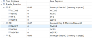
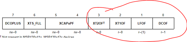
If there is only one crystal in the system it should be connected to LFXT1. Using
only XT2 causes the LFOF fault flag to remain set, not allowing for the OFIFG
to ever be cleared.
To use the XT2 pins for connecting the G1 crystal comes from a former design which is already in the field and is running without issues.
I