This thread has been locked.

If you have a related question, please click the "Ask a related question" button in the top right corner. The newly created question will be automatically linked to this question.

MSP430FR2676: Mutual backchannel UART and troubles with 8x8 mutual button array

Part Number: MSP430FR2676
Other Parts Discussed in Thread: CAPTIVATE-FR2676

This is mostly a continuation from another post linked here : https://e2e.ti.com/support/microcontrollers/msp-low-power-microcontrollers-group/msp430/f/msp-low-power-microcontroller-forum/1067078/msp430fr2676-backchannel-uart-for-8x8-mutual-capacitance-array/3948322#3948322

I had thought all my problems were solved.

I have two problems currently.

1) I can't get 8x8 mutual array to work where I am able to get 2x2, 4x4, and 6x6 to work just fine. I have noticed when I go to 8x8 my cpu usage does go up to 100% so I am assuming my computer simply can't handle the data visualization in the captivate design studio? (this is a different project then the attached zip, used for tuning) (I am hoping the backchannel UART as attached will work as it wont go trough the design center to display the information and simply send data without visualization if my computer is the limiting factor) 

2) This is the problem continuation from the post mentioned above, I have UART_ENABLE=true in my predefined symbols and include the demo folder in include options but am still getting unresolved symbol errors regarding these. I attached a zip file of my CCS project. The layout for the design center is the same as the previous post. (I was utilizing the example backchannel UART to ensure I had the same predefined symbols and included paths)

MSP430FR2676_8X8_Mutual_UART.zip

  • Hi Alex,

    Can you post the errors you are getting?

  • Hi Alex,

    I'm not sure why you are getting these errors.  Something is not set correctly and so rather than continue to chase our tails on this one, I have attached a "working" 8x8 trackpad project you can see how to make this works.

    I started from scratch and generated my project in Captivate design center GUI.

    I created a callback in demo.c

    Then I made the following changes to make it possible to send whatever I choose in my callback out through the UART.

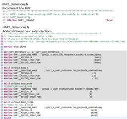
    In UART_Definitions.h I uncommented out line #69 and add new definitions for the UART.  Note, these are based on 2MHz SMCLK

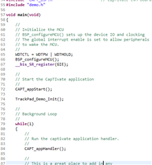
    Next, in main.c I add #include "demo.h" and a call to TrackPad_Demo_Init();

    Take a look at my callback in demo.c to see how to grab the sensor parameters and send them out through the UART.

    I attached my project.

    TP8X8_FR2676_01_83_00_08.zip

  • It's working with no errors but still am not seeing anything through the terminal, I know it is operational as I can see LED2 light up after I touch the array (although seems to be a 23 second delay). The delay is probably on my end with my current sensor design. I have the device manager telling me the MSP UART is com13, so I have a serial port at 19200 baud, no parity, data size 8 and am not seeing anything pop up in the terminal.

  • Alex, if you are running the MSP430 in debug mode you will see long delays in the UART data.  Program the MSP430 for normal operation (not in debug mode) and see it that helps.

  • I am going to run>load>project, I assumed this was just loading the code onto the chip and not apart of debug right?

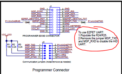
  • Yes, that should be fine.  Are you using the CAPTIVATE-FR2676 EVM module by chance?  If so, there is a small modification to the PCB you must perform before you can send data using the back-channel uart.  Do you have R24/R25 populated?

  • R24 and R25 are currently unpopulated. Will soldering resistors for R24 and R25 remove other functionality? What value resistors should be put here?

  • Hi Alex,

    Normally, the MSP430 UART signals P1.4/UCA0TXD and P1.4/UCA0RXD go through jumper J2 and then to the 20-pin connector J1 pins 8 and 7 respectively. This is the primary communications path between the MSP430 and the HID Bridge device on the programmer PCB that translates the UART to USB HID and sends to the GUI. 

    The resistors R24 and R25 are DNP by default, but if you populate them with a 0 ohm resistor (or piece of wire), then the TXD and RXD signals will now also route to J2 pins 9 and 10 (EZFET_TXD and EZFET_RXD).  That is the communications path between the MSP430 and the back-channel UART on the programmer.  But, you need to first remove the two jumpers on J1 (1-2) and (3-4) to disconnect the UART from the GUI.

    Is this clear?

  • I soldered in some wire for R24 and R25. You mean remove the two jumpers on J2 the TXD and RXD correct? I did this and am now seeing information in the terminal but that information is just a bunch of random symbols and characters it seems? 

  • Hi Alex,

    Exactly.  That's because you are sending the data that normally is transmitted to the GUI over the HID_Bridge_UART but now is going through the programmer's back-channel UART.  You need to modify CAPT_UserConfig.h and set CAPT_INTERFACE to either NO or BULKI2C if you want to send GUI data to the GUI while you use the UART for your application data (hint - open the zip file I attached earlier in this thread) and follow the instructions at the top of this thread to use the UART for your data.

  • I have CAPT_INTERFACE set as (__CAPT_NO_INTERFACE__) in CAPT_UserConfig.h , I don't intend on receiving GUI data, just the data I am after. I would assume if it was transmitting the GUI data it would be a constant stream of data and not just sending data when the sensor detects a touch as indicated by the green LED right?

  • Hi Alex,

    Ok, if you only see data being transmitted when you touch, this is good.  It means you are sending your data to the PC, although scrambled.  So this tells me the MSP430 and the PC are not using the same baud rate.  Can you confirm this?

  • I'm unsure as to what you mean, I know you defined the baud rate in UART_Definitions.h and have it set at 19200. The serial terminal I am opening is also set at 19200, I did try 9600 as well (changing the value we defined in UART_Definitions and terminal to 9600). I also have the encoding set to ASCII.

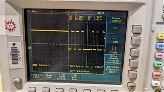
  • What terminal application are you using on the PC?  Make sure PARITY = none.  Also, if you have a logic probe or oscilloscope, take a look at the TXD pin and you should see a series of pulses going from 3.3v to gnd.  Some pulses will be narrow than others.  Locate the narrowest pulse.  If you measure the period it should be 52uS @ 19200.

  • The settings I have been using are baud rate 19200, data size 8, parity none, stop bits 1, and ASCII encoding. I have tried CCS terminal, tera term, and using command prompt to open a serial terminal. I'll try and get ahold of an oscilloscope.

  • Hi Alex,

    Just checking to see if you had a chance to measure the baud rate on the TXD pin with an oscilloscope?

  • Hey Dennis,

    I was able to check it just now, this is what I am seeing for 52us.

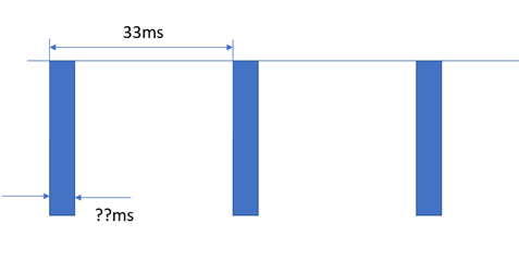
  • Excellent.  52us is 19200 baud which is what it should be. We are running out of things to try, but here is one more.  Take your scope and zoom out so you can capture a packet of bytes.  You should see them come along every 33ms or 20ms (whatever you have set for the sensor scan rate).  Measure the time from beginning of the packet to the end.  How many ms is it?

  • It's showing 33ms

  • Hi Alex,

    Here is what I mean.  What is ??ms

  • Dennis,

    I see what you mean now, I am measuring 440 us 

  • Ok, good.  If we take 440us/52us it is ~8.46, which is close to the 8 bytes being transmitted to the GUI, which tells me that CAPT_INTERFACE is not set to (__CAPT_NO_INTERFACE__).

    I have CAPT_INTERFACE set as (__CAPT_NO_INTERFACE__) in CAPT_UserConfig.h

    So, the simplest way to settle this go into the callback function and where you are preparing your ASCII data to send using the UART, comment out the line that uses UART_transmitBuffer function. This means you should not be sending any data and you should not see anything on the scope. 

    Give that a try and let me know what you see.

  • Alright, I commented out the UART_transmitBuffer function in demo.c and no longer get anything printed to the terminal and nothing on the oscilloscope. 

  • Hi Alex,

    Ok, let's recap.  You measured packets being sent from the UART every 33msec.  We confirmed the UART baud rate is 19200.  You just confirmed that the data being sent is your data coming from the callback and not the sensor data that is sent to the GUI.  This all points to something on the receiving (PC) side as not being correct if you are just getting random junk symbols.

    The very last thing you can try, if you want to make absolutely sure the data is correct is use a logic probe that will capture the packet and decode the ASCII characters to see what is actually being sent.

    Are you sure you are using something like my example "demo.c" file?  You aren't sending the raw binary sensor values, are you?  Can you post that portion of your code in your callback that transmits the data?

  • I am using the code you sent me, I thought it best to get that working before making any changes. Here is the code:

    /*
    * Trackpad_demo.c
    *
    * This file contains the sensor callbacks, UART and slave I2C communications handler
    * to support communications with host.
    * Note: See the modification to CAPT_commConfig.h on line #84 to enable both I2C and UART
    * To control and data format and interface (HID, UART or I2C), refer to setup.h
    *
    * Created on: Feb 9, 2017
    * Author: a0272918
    */
    #include "captivate.h"
    #include "CAPT_UserConfig.h"
    #include "CAPT_BSP.h"
    #include "UART.h"
    #include <stdio.h>

    //======================== DEFINES ========================================
    #define FIRST_SENSOR_TOUCH (pSensor->bSensorTouch == true) && (pSensor->bSensorPrevTouch == false)
    #define SENSOR_TOUCH (pSensor->bSensorTouch == true) && (pSensor->bSensorPrevTouch == true)
    #define EXIT_TOUCH (pSensor->bSensorTouch == false) && (pSensor->bSensorPrevTouch == true)
    #define NO_TOUCH TOUCH (pSensor->bSensorTouch == false) && (pSensor->bSensorPrevTouch == false)

    //======================= VARIABLES ========================================
    uint8_t asciiBuffer[32];
    uint16_t ui16Position_X;
    uint16_t ui16Position_Y;
    uint8_t ui8Gesture;

    // Added this so when switching back to GUI interface, this code doesn't cause compiler warnings
    #if CAPT_INTERFACE != (__CAPT_UART_INTERFACE__)
    /*
    * CREATE A LOCAL INSTANCE OF UART PARAMETERS
    */
    static const tUARTPort UARTPort =
    {
    .pbReceiveCallback = NULL,
    .pbErrorCallback = 0,
    .peripheralParameters.selectClockSource = EUSCI_A_UART_CLOCKSOURCE_SMCLK,
    .peripheralParameters.clockPrescalar = UART__PRESCALER,
    .peripheralParameters.firstModReg = UART__FIRST_STAGE_MOD,
    .peripheralParameters.secondModReg = UART__SECOND_STAGE_MOD,
    .peripheralParameters.parity = EUSCI_A_UART_NO_PARITY,
    .peripheralParameters.msborLsbFirst = EUSCI_A_UART_LSB_FIRST,
    .peripheralParameters.numberofStopBits = EUSCI_A_UART_ONE_STOP_BIT,
    .peripheralParameters.uartMode = EUSCI_A_UART_MODE,
    .peripheralParameters.overSampling = UART__SAMPLING_MODE
    };
    #endif

    //=========================== CALLBACKS =======================================
    /*
    * TRACKPAD CALLBACK
    * AUTOMATICALLY CALLED AFTER SENSOR IS PROCESSED
    * ADD APPLICATION SPECIFIC CODE HERE
    */
    void trackpad_callback(tSensor* pSensor)
    {

    tTrackPadSensorParams* pSensorParams = (tTrackPadSensorParams*)pSensor->pSensorParams;
    uint8_t ui16BufferLength;

    // If using the MSP430FR2676 EVM module, show when there is a touch
    if(FIRST_SENSOR_TOUCH == true)
    LED2_ON;

    else if(SENSOR_TOUCH == true)
    {
    /* Get the reported gesture */
    ui8Gesture = ((tTrackPadSensorParams*)(pSensor->pSensorParams))->ui8Gesture;

    /* Clear the gesture (set = 0xFF) after reading to reset for next gesture */
    ((tTrackPadSensorParams*)(pSensor->pSensorParams))->ui8Gesture = 0xFF;

    ui16Position_X = pSensorParams->Position_X.ui16Natural;
    ui16Position_Y = pSensorParams->Position_Y.ui16Natural;

    ui16BufferLength = sprintf((char*) asciiBuffer, "%d %d %d\r\n\0", ui8Gesture, ui16Position_X, ui16Position_Y );

    UART_transmitBuffer(asciiBuffer,ui16BufferLength);

    }
    else

    LED2_OFF;


    }


    void TrackPad_Demo_Init(void)
    {
    //
    // REGISTER THE TRACKPAD CALLBACK HERE
    // REGISTERING THESE CALLBACKS ALLOWS THE USER FUNCTIONS
    // TO BE CALLED EACH TIME AFTER A SENSOR IS MEASURED REGARDLESSS
    // IF THE SENSOR IS TOUCHED OR NOT

    MAP_CAPT_registerCallback(&TKP00, &trackpad_callback);


    #if CAPT_INTERFACE != (__CAPT_UART_INTERFACE__)
    UART_openPort(&UARTPort);
    #endif

    }

  • Hi Alex,

    Let's try this..  Here is the code for reference.

    #include <msp430.h>                      // Generic MSP430 Device Include
    #include "driverlib.h"                   // MSPWare Driver Library
    #include "captivate.h"                   // CapTIvate Touch Software Library
    #include "CAPT_App.h"                    // CapTIvate Application Code
    #include "CAPT_BSP.h"                    // CapTIvate EVM Board Support Package
    #include "UART.h"
    #include <stdio.h>
    
    #define UART__EUSCI_A_PERIPHERAL                                (EUSCI_A0_BASE)
    #define UART__LPMx_bits                                             (LPM0_bits)
    // These values are base on SMCLK = 2MHz
    #ifdef UART__SAMPLING_MODE
    #undef UART__SAMPLING_MODE
    #endif
    #define UART__SAMPLING_MODE    (EUSCI_A_UART_OVERSAMPLING_BAUDRATE_GENERATION)
    #ifdef UART__PRESCALER
    #undef UART__PRESCALER
    #endif
    #define UART__PRESCALER                                                  (0x06)
    #ifdef UART__FIRST_STAGE_MOD
    #undef UART__FIRST_STAGE_MOD
    #endif
    #define UART__FIRST_STAGE_MOD                                            (0x08)
    #ifdef UART__SECOND_STAGE_MOD
    #undef UART__SECOND_STAGE_MOD
    #endif
    #define UART__SECOND_STAGE_MOD                                           (0x17)
    static const tUARTPort UARTPort =
    {
        .pbReceiveCallback = NULL,
        .pbErrorCallback = 0,
        .peripheralParameters.selectClockSource = EUSCI_A_UART_CLOCKSOURCE_SMCLK,
        .peripheralParameters.clockPrescalar = UART__PRESCALER,
        .peripheralParameters.firstModReg = UART__FIRST_STAGE_MOD,
        .peripheralParameters.secondModReg = UART__SECOND_STAGE_MOD,
        .peripheralParameters.parity = EUSCI_A_UART_NO_PARITY,
        .peripheralParameters.msborLsbFirst = EUSCI_A_UART_LSB_FIRST,
        .peripheralParameters.numberofStopBits = EUSCI_A_UART_ONE_STOP_BIT,
        .peripheralParameters.uartMode = EUSCI_A_UART_MODE,
        .peripheralParameters.overSampling = UART__SAMPLING_MODE
    };
    
    extern void TrackPad_Demo_Init(void);
    void main(void)
    {
    
    	WDTCTL = WDTPW | WDTHOLD;
    	BSP_configureMCU();
    	UART_openPort(&UARTPort);
    	__bis_SR_register(GIE);
    
    	while(1)
    	{
    	    UART_transmitBuffer("hello world\n", 12);
    	    _delay_cycles(10000000);
    	}
    
    } // End main()
    

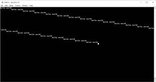
    Make a copy of your project (or the one I had provided sometime earlier) and replace the main.c with this code.  Rebuild and program the MSP430 if you connect your PC and configure the COM port to 19200, 8N1.  You should see something like this:

    If not, you have a problem with your setup or PC configuration.

  • That does work, although slightly different formatting.

**Attention** This is a public forum