Hi experts,
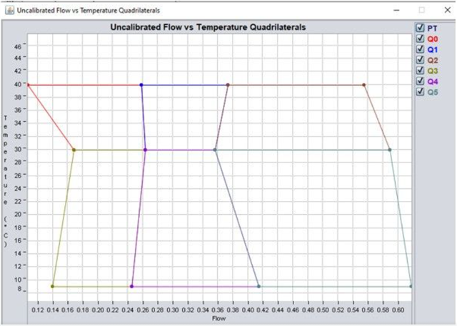
we are trying to calibrate a meter with flow and temeperature and following the instruction in the documentation we got this
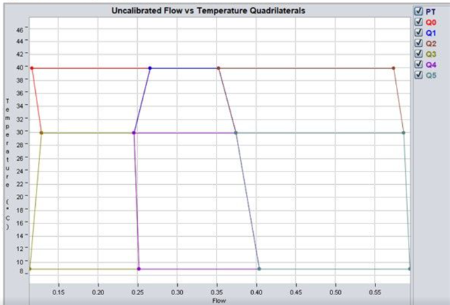
we are in testing stage so the fig above is only for 3 meters in the future we will use at least 20 and more temperatures and flows, we also have the individual quadrilaterals.

meter #1
meter #2

meter #3
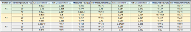
values.
The issue is when we try to use the function USS_computeTemperature(config, &fixedResults) to estimate the temperature, we got values below -60 °C

date, -> calibrated flow(l/s), non calibrated flow(l/s), estimated temperature(°C), code error.
As reference the reference meter shows 0.630 l/s at 6 °C
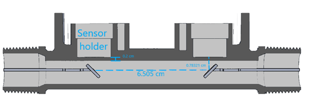
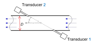
the dimensions of our meter are:
pipe diameter (2 * r) : 1/2 ''
distance between reflectors (L) : 6.505 cm

any suggestions?