This thread has been locked.

If you have a related question, please click the "Ask a related question" button in the top right corner. The newly created question will be automatically linked to this question.

MSP430FR2355: Single Chip Pulse Oximeter Using MSP430fr2355

Part Number: MSP430FR2355


Hi,

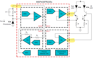
Im following the application note Slaae25 provided by ti. To build a single chip Pulse Oximeter using msp430fr2355.

I've used the code provided in the document. Im attaching below the output that im getting on the GUI.
And the shiled that we developed to interface with MSP430expfr2355 evaluation board.

The PPG signal cannot be viewed clearly and the output is saturated. Guide me where I'm going wrong.

Application Note:Slaae25.pdf

  • Hi,

    I would suggest you to check your hardware first. 

    You can use an oscillator to read the current on the photodiode. The current is small however, with a good oscillator you can read out the current. 

    Best regards,

    Cash Hao

  • Hi, I checked the hardware connections and discovered that the OA2O is not connected with A0 (pin2). as it is not present on the pin outs of the MSP430EXPFR2355 Evaluation board. but is connected directly to the LED on the evaluation kit.
    but when I see the block diagram provided in the application note its clear that the output of TIA is internally connected with ADC convertor. So why is this Connection needed. Please explain 

  • Hi,

    There is a mark error on the figure 4-1 which is the Block Diagram. It should be SAC2 instead of SAC0 as the TIA. SAC0 should be the gain stage. 

    Best regards,

    Cash Hao

  • Hello, while designing our PCB layout we did make those consideration that SAC2 is used as a TIA. But my concern here is if the output of SAC2 is internally connected to A0(ADC convertor) , why do we still need to connect it externally?

    Thanks.

  • Hello,

    The above doubt raised was cleared to me.

    As far as the hardware is concerned ive cross verified every single thing in it and all the possible errors have been debugged.

    Except that we are using a 1pF feedback capacitance in the TIA instead of 3pF.( Recommended).

    Using 1pF feedback capacitance is giving a stable output, flat signal on the GUI in absence of a finger, and the output is consistent. But the output with a finger is inconsistent.

    Due to the unavailability of a 3pF capacitance i made ah parallel connection of 3 1pF capacitance but that isn't making any difference rather Making the output even more unstable, and unpredictable even in absence of a finger.(which was stable with1pF capacitance)

    The code provided by ti is used as it is, but still there is no consistent output.

    Please help.

    OUTPUT WITH 1pF feedback capacitor for TIA.

    WHEN NO FINGER IS PRESENT


    OUTPUT WHENC FINGER IS PRESENT 

    READING 1;

    READING 2

    READING 3

    OUTPUT WITH 3pF.

    READING 1

    READING 2

  • Hi,

    I still strongly recommend you to use an oscillator to read out the current on the photodiode. And compare to the ADC data. If the data match each other, then it would be a hardware issue, including fixture, Red and IR LEDs. 

    Best regards,

    Cash Hao

  • Is it an oscillator or an oscilloscope ? And if I want to measure the current using an oscilloscope shall i measure the voltage across the feedback resistor of TIA and then divide by R2 = 1Mohm   to get the current? Or is there some other way ? 

    oscilloscope probes at OA20 and OA2- to measure voltage across  it?

    Thanks.


  • Hi,

    I mean to use an oscilloscope. Measure the voltage on R2 should work.

    Best regards,

    Cash Hao

  • Thanks,

    I did as you recommended and this is the voltage Waveform that I've obtained.

    Channel 1 (Yellow) represents Voltage at OA20 with resect to ground.             Vlow = 1.2V      Vhigh = 3.5V

    Channel 2 (Blue) represents Voltage at OA2-    with respect to ground.            Vlow =485mV   Vhigh = -190mV

    math function is Channel1 - Channel2 (difference between the two voltages).  Vlow=715mV     Vhigh= 3.54V  

                                                                                                           current Id      Idlow =.715mA  Idhigh= 3.54mA

    The Voltage at OA2- should be a constant of 483mV its coming out to be close to that value.

    Can you explain why is it falling below that value? 

    And How do i use the data to compare the ADC converted output on the GUI? What should be my next Step.

    Corresponding GUI.

    Please Guide 


  • Hi,

    Your signal looks fine on the oscilloscope. 

    You need to check the TIA signal instead of the PPG signal in the GUI. The default gain setting for the PPG is 32x. It looks like the data is overflowed after gain stage. 

    Best regards,

    Cash Hao

  • Hi,

    This is the output which I'm getting can you help me figure out what does the readings on the Y-axis imply ? and how do I convert them to voltage ? 

    The number on the x axis represents samples?

    If it is the digital output how do I scale it in terms of Voltage?

    Thanks. 


  • Hi,

    Your PPG signal looks normal now. The data showed in your figure should be the the full PPG signal with (AC+DC). You can read the find the function PPG_recoverFullSignal in the code for more details. 

    Yes, X axis represents samples.

    Best regards,

    Cash Hao

  • Hello,

    I can understand the data on the y axis is in the Digital format. But I want to convert it into analog can you help me make atleast one conversion.

    I have obtained the formula from the user guide which shows ADC conversion.

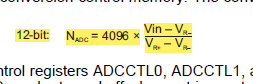
          but when I use this formula to obtain Vin, I'm getting value near 11V.

    Please explain.

     Thanks.

  • Hi,

    Like I said, Please check the code.

    Best regards,

    Cash Hao

  • Hi,

    I went through this part of the code. And I now understand that the PPG signal is basically GAIN x Vo(SAC2, TIA).  So to convert this digital data into volt im using the formula posted below.

    And on conversion im getting values within 3.3V.  Is this Formula correct.?

    Thanks. 

  • Hi,

    You formula is for the AC signal and it is correct. But the PPG signal is (AC+DC) signal after a FIR filter. You can check the code I posted before onthe ir_ppg->signal and vs_ppg->signal.

    Best regards,

    Cash Hao

  • Hi, 

    I'am facing a difficulty in obtaining a stable PPG waveform, at some instances i get the Waveform perfect and at other instance i get no wave. I thought it was due to the self assembled SpO2 finger clip. And so I switched to a commercial SpO2 finger clip, but achieved nothing. I will attach the system I used before and the current system. Please suggest what shall I do further.

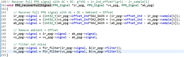
     this is the system with a commercial probe.  and this is self assembled Spo2 probe.

       these are the output even when Iam using commercial SpO2 finger clip.

    Thanks.

**Attention** This is a public forum