Part Number: MSP430FR2433
I am currently developing a door magnetic switch using msp430fr2433.(Environment: CCS10.4.0)
Firstly, I tried to use driverlib to speed up my development. As two buttons on launchpad are linked to P2.3 and P2.7, the example code run well last week and I thought it was simple.
However, there is another button linked to P1.1 on my own hardware. I tried to modify code like this.
void main (void)
{
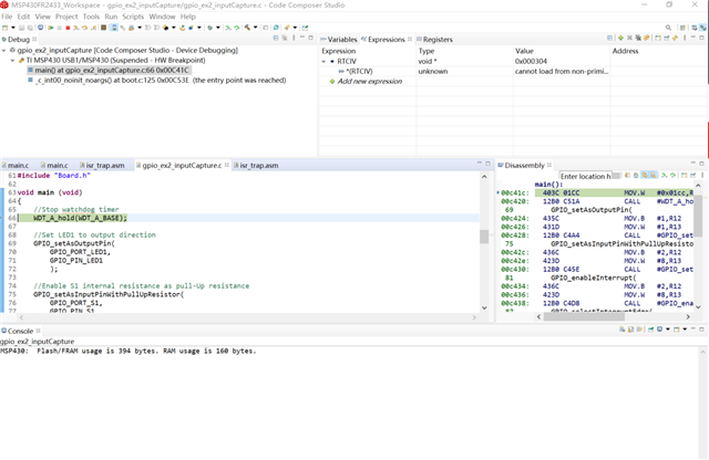
//Stop watchdog timer
WDT_A_hold(WDT_A_BASE);
//Set LED to output direction
GPIO_setAsOutputPin(GPIO_PORT_P1,GPIO_PIN0 + GPIO_PIN1);
//Set LED pins HI
GPIO_setOutputHighOnPin(GPIO_PORT_P1,GPIO_PIN0 + GPIO_PIN1);
//Enable S1,S2 internal resistance as pull-Up resistance
GPIO_setAsInputPinWithPullUpResistor(GPIO_PORT_P1,GPIO_PIN5);
GPIO_setAsInputPinWithPullUpResistor(GPIO_PORT_P2,GPIO_PIN2 + GPIO_PIN3 + GPIO_PIN7);
//S1,S2 interrupt enabled
GPIO_enableInterrupt(GPIO_PORT_P1,GPIO_PIN5);
GPIO_enableInterrupt(GPIO_PORT_P2,GPIO_PIN2 + GPIO_PIN3 + GPIO_PIN7);
//S1 Hi/Lo edge
GPIO_selectInterruptEdge(GPIO_PORT_P1,GPIO_PIN5,GPIO_HIGH_TO_LOW_TRANSITION);
GPIO_selectInterruptEdge(GPIO_PORT_P2,GPIO_PIN2 + GPIO_PIN3 + GPIO_PIN7,GPIO_HIGH_TO_LOW_TRANSITION);
//S1 IFG cleared
GPIO_clearInterrupt(GPIO_PORT_P1,GPIO_PIN5);
GPIO_clearInterrupt(GPIO_PORT_P2,GPIO_PIN2 + GPIO_PIN3 + GPIO_PIN7);
PMM_unlockLPM5();
//Enter LPM3 w/interrupt
__bis_SR_register(LPM3_bits + GIE);
//For debugger
__no_operation();
}
#if GPIO_PORT_S1 == GPIO_PORT_P1
//******************************************************************************
//
//This is the PORT1_VECTOR interrupt vector service routine
//
//******************************************************************************
#if defined(__TI_COMPILER_VERSION__) || defined(__IAR_SYSTEMS_ICC__)
#pragma vector=PORT1_VECTOR
__interrupt
#elif defined(__GNUC__)
__attribute__((interrupt(PORT1_VECTOR)))
#endif
void P1_ISR (void)
{
__delay_cycles(10000);
GPIO_toggleOutputOnPin(GPIO_PORT_P1,GPIO_PIN0 + GPIO_PIN1);
GPIO_clearInterrupt(GPIO_PORT_P1,GPIO_PIN5);
}
#elif GPIO_PORT_S1 == GPIO_PORT_P2
//******************************************************************************
//
//This is the PORT2_VECTOR interrupt vector service routine
//
//******************************************************************************
#if defined(__TI_COMPILER_VERSION__) || defined(__IAR_SYSTEMS_ICC__)
#pragma vector=PORT2_VECTOR
__interrupt
#elif defined(__GNUC__)
__attribute__((interrupt(PORT2_VECTOR)))
#endif
void P2_ISR (void)
#endif // #if GPIO_PORT_S1
{
__delay_cycles(10000);
if (GPIO_getInterruptStatus(GPIO_PORT_P2 , GPIO_PIN2))
{
GPIO_toggleOutputOnPin(GPIO_PORT_P1,GPIO_PIN0 + GPIO_PIN1);
if (GPIO_INPUT_PIN_HIGH == GPIO_getInputPinValue(GPIO_PORT_P2 , GPIO_PIN2))
{
GPIO_selectInterruptEdge(GPIO_PORT_P2,GPIO_PIN2,GPIO_HIGH_TO_LOW_TRANSITION);
}
else
{
GPIO_selectInterruptEdge(GPIO_PORT_P2,GPIO_PIN2,GPIO_LOW_TO_HIGH_TRANSITION);
}
}
if (GPIO_getInterruptStatus(GPIO_PORT_P2 , GPIO_PIN3))
{
GPIO_toggleOutputOnPin(GPIO_PORT_P1,GPIO_PIN0);
if (GPIO_INPUT_PIN_HIGH == GPIO_getInputPinValue(GPIO_PORT_P2 , GPIO_PIN3))
{
GPIO_selectInterruptEdge(GPIO_PORT_P2,GPIO_PIN3,GPIO_HIGH_TO_LOW_TRANSITION);
}
else
{
GPIO_selectInterruptEdge(GPIO_PORT_P2,GPIO_PIN3,GPIO_LOW_TO_HIGH_TRANSITION);
}
}
if (GPIO_getInterruptStatus(GPIO_PORT_P2 , GPIO_PIN7))
{
GPIO_toggleOutputOnPin(GPIO_PORT_P1,GPIO_PIN1);
if (GPIO_INPUT_PIN_HIGH == GPIO_getInputPinValue(GPIO_PORT_P2 , GPIO_PIN7))
{
GPIO_selectInterruptEdge(GPIO_PORT_P2,GPIO_PIN7,GPIO_HIGH_TO_LOW_TRANSITION);
}
else
{
GPIO_selectInterruptEdge(GPIO_PORT_P2,GPIO_PIN7,GPIO_LOW_TO_HIGH_TRANSITION);
}
}
GPIO_clearInterrupt(GPIO_PORT_P2,GPIO_PIN2 + GPIO_PIN3+GPIO_PIN7);
}
I downloaded this code to my launchpad. Two new buttons: P2.2 and P1.5, I used DuPont cable to short them to GND instead of pressing buttons.
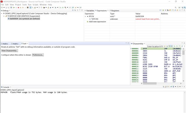
Then some problem occured. The code doesn't run well and in debug view, the code stopped at JMP __TI_ISR_TRAP in isr_tram.asm
I just press start and suspend in the debug view and didn't press any button on my hardware.
I tried again to the original example and it seems to the same problem.
I also tried the example without driverlib: msp430fr243x_P1_03.c but failed just the same.
I'm confused why this happened and I'm sure there's nothing happened to my computer this weekend.