This thread has been locked.

If you have a related question, please click the "Ask a related question" button in the top right corner. The newly created question will be automatically linked to this question.

blood flow metering

Part Number: MSP430FR6047
Other Parts Discussed in Thread: EVM430-FR6043, SN74LVC2T45

Hi, I'm reading documents about MSP430FR6047 and evaluation board of that to use for blood flow metering and I faced with some questions.

First Question: Is there any configuration to change value of speed of sound in water to speed of that in blood? I couldn't find such variable in Ultrasonic Sensing Design Center (GUI).

Second problem: Where can I set the distance that sound travel in Fluid (Blood). You know to calculate velocity of flow we need to length of distance that sound travels in flow. But It seems there isn't any parameter for this purpose in GUI?! Is there any parameter in Coding Part? It is very important because the system can be used to measure a thick pipe's flow or thin one. Therefore, the time of sound travel in body of pipe will be different and this affect measurements.

Third: also cosine of piezo angle needs in formula of flow metering by Delta TOF.

fourth: In clamp on water meter for PVC pipes application report (slaa949) have been showed an experiment that piezos used in clamp on method. The output of MSP430 piezo driver has an approximately 2.5 volt pin. But we know driving piezos mostly needs higher voltages. Is there any amplifier used in this test? or the used piezos can be excited with lower voltage?

best regards

  • Hi Thomas

    1~3: the same issue,  use GAP between pulse start and ADC capture to decide when adc is on, we don't use distance and speed.

    4: no amplifier used in that case, we  also used ultrasonic couplant gel between piezos and pipe.

    Best regard

    Joe


  • Thanks for your prompt reply. There are some other questions that please clarify the answer.
    1. Is it possible to add an amplifier module to excite transducers with higher voltage without causing damage to the board? Does it need a relay or analog switch to prevent damage to the receiver circuit of IC? What should we change in GUI?
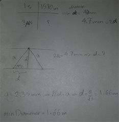
    2. The TI website has expressed about EVM430-FR6043:"Ability to support a wide pipe sizes with 15‑mm to 1000 mm diameter". But in the GUI (Ultrasonic Sensing Design Center - Water Mode), "Gap between pulse start and ADC capture (us)" parameter can take 3us as min value. This time approximately proportional to 1.5 millimeters distance for V transducer configuration.
    Which one is correct? Is there a reason why at least 15 mm of pipe diameter is stated in the specifications? For our work, it is necessary to measure thin vessels.

    Min Pipe SizeMin Pipe Size Based on GUI

    3. There is a parameter in the GUI that can enter "Sound Velocity in medium (m/sec)". But this section is inactive. Will this section be activated after connecting the board to the computer and will it be possible to set the value?

    Sound Velocity in Medium


    4. Based on your previous answer, can we say that the angle of the piezo with the pipe can be selected as any desired value, such as 45, 63 or 30 degrees?

    Best regards

    Thomas

  • Hi Thomas,

    1. Is it possible to add an amplifier module to excite transducers with higher voltage without causing damage to the board? Does it need a relay or analog switch to prevent damage to the receiver circuit of IC? What should we change in GUI?

    I would suggest to add a voltage level shift for a higher excitation voltage like the one in the EVM430-FR6043 board. You can choose the VCC-TX at 5V, and use the SN74LVC2T45 as the level shifter. Adding these might cause zero flow drift issue through temperatures. However, in your application, the temperature should be limited in a short range. It would not cause much problem. 

    2. The TI website has expressed about EVM430-FR6043:"Ability to support a wide pipe sizes with 15‑mm to 1000 mm diameter". But in the GUI (Ultrasonic Sensing Design Center - Water Mode), "Gap between pulse start and ADC capture (us)" parameter can take 3us as min value. This time approximately proportional to 1.5 millimeters distance for V transducer configuration.
    Which one is correct? Is there a reason why at least 15 mm of pipe diameter is stated in the specifications? For our work, it is necessary to measure thin vessels.

    Both of them are correct. In residential water meter, 15mm is commonly used as the minimum pipe size.  The min Gap between pulses start and ADC capture can be set as 3us. It is capable to measure a 1.5mm distance between transducers. However, it is very hard to implement your flow meter on such a small pipe. Besides, the longer distance the better accuracy. With such a small distance, you need to consider a lot more things. I would recommend at least 20us of absTOF for your pipe design. 

    3. There is a parameter in the GUI that can enter "Sound Velocity in medium (m/sec)". But this section is inactive. Will this section be activated after connecting the board to the computer and will it be possible to set the value?

    You need to enable the volume flow rate calibration function in the software to set this parameter. 

    4. Based on your previous answer, can we say that the angle of the piezo with the pipe can be selected as any desired value, such as 45, 63 or 30 degrees?

    Yes, the angle is not limited. But, a longer distance between transducers is preferred. 

    Best regards,

    Cash Hao

**Attention** This is a public forum