Part Number: MSP-EXP430F5529LP
Other Parts Discussed in Thread: MSP430F5529, , MSP430WARE
Thanks in advance for help here.
I am building a custom board with an MSP430F5529 that has an I2C communication bus. After having trouble communicating, I purchased a MSP-EXP430F5529LP to help remove any hardware problems from my code development. I am finding that I have the same problem on the MSP-EXP430F5529LP. Here is what I am doing:
In CCS I have loaded the I2C example from MSP430 ware at the following location: "C:\ti\msp430ware_3_80_14_01\examples\devices\MSP430F5xx_6xx\MSP430F55xx_Code_Examples\C\MSP430F55xx_usci_i2c_standard_master.c"
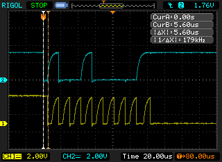
Following the hardware prescription in the header, I have Pin 3.0 for SDA and Pin 3.1 for SCL with 4.7k pull-up resistors. I have connected my oscilloscope to SDA and SCL. Upon initialization, SDA and SCL hold a steady 3.3V as expected. Using the debugger, I am stepping through the first I2C write function (I2C_Master_WriteReg). When I execute the line:
UCB0CTL1 |= UCTR + UCTXSTT; // I2C TX, start condition
SCL drops to zero volts. Then on the following line:
__bis_SR_register(LPM0_bits + GIE); // Enter LPM0 w/ interrupts
CCS hangs with no progress. I was surprised to see SCL drop to zero volts, since I thought the start condition for I2C should pull SDA to zero for the start condition. Is there something I am missing here? I am unsure if there is a mapping problem or if I am missing something simple. FYI, in this debug setup I outlined here, I do not have a slave connected to the I2C bus, but I am watching for serial data to be communicated with my Oscope.
Any input is appreciated!
John