Other Parts Discussed in Thread: MSP-FET, MSP430FR5962, MSP430FR5964, MSP430FR5994, MSP430FR5992,
When I have the MSP-FET connected to the MSP430, the chip responds properly to low reset pulse. The chip resets and starts execution as it should. When the MSP-FET is disconnected the MSP430 will go into reset, but will not comeout. It does nothing. Basically what the chip would do if it were stuck in reset.
The elctrical document (MSP430FR5994, MSP430FR59941, MSP430FR5992, MSP430FR5964, MSP430FR5962
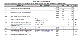
SLASE54D – MARCH 2016 – REVISED JANUARY 20) has little to no information about the reset operation. It simply states the reset line should be held low for 2uSec. It say's nothing about what voltage levels cause what action.
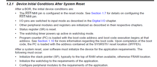
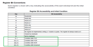
The programming document (SLAU367P – October 2012 – Revised April 2020) say's a little more, but nothing about the electricakl operation of the reset signal. The SFRRPCR register remains untouched by the running code. (Set for RST, with a pull-up enabled.)
When the MSP-FET is connected, the low-reset occurs, the line goes to tristate (middle value), then to the high VCC level.
Whitout the MSP-FET connected, the low-reset is followed by the line going to 2/3 VCC. The line has an external AND the internal pullup. (But it is not goig to VCC.) The only other external component is a capacitor connected to Gnd. So why doesn't the line go to VCC?
What is going on inside the MSP430's RST line?
Where can I find the electrical min/max for the reset line?
Where can I find the electrical characteristics of the RST line? (RST is starts at ?VCC, RST terminates at ?VCC,..)
Thank you