I encountered the following problems when using MSP430FR2111IPW16 microcontroller, please help to answer them, thank you.
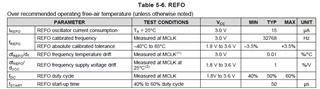
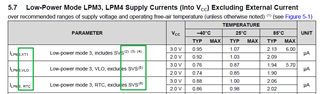
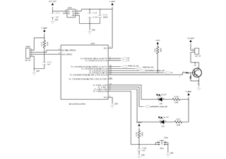
1.My program all the pins have been carried out in accordance with the schematic diagram in the correct configuration,the active pattern with low power consumption MCU current around 2 ua 4 mode, it is in conformity with the prospectus shows the current value, but if 3 into low power mode, the current is about 20 ua, it's not conform to the description of current value, this kind of phenomenon is not normal. It doesn't meet my standards.
2.My interrupt button is triggered by falling edge. Pull-up resistance has been added to the circuit, but an external interrupt will be triggered every time I supply power to the single chip microcomputer. Could you please help to
answer the reason?
#include "msp430.h"
void All_Init(void);
int main(void)
{
All_Init();
__bis_SR_register(LPM3_bits+GIE); Low power 3 mode current is 22uA
//__bis_SR_register(LPM3_bits+GIE); Low power 4 mode current is 2uA
while(1)
{
}
}
void All_Init(void)
{
WDTCTL = WDTPW | WDTHOLD;
//SYSCFG0 = FRWPPW;
FRCTL0=FRCTLPW | NWAITS_1;
__bis_SR_register(SCG0);
CSCTL0 = 0x00;
CSCTL1 &= ~(DCORSEL_7);
CSCTL1 |= DCORSEL_5;
CSCTL2 = FLLD_0 + 487;
CSCTL3 = SELREF__REFOCLK;
__delay_cycles(3);
__bic_SR_register(SCG0);
while(CSCTL7 & (FLLUNLOCK0 | FLLUNLOCK1));
CSCTL4 = SELMS__DCOCLKDIV | SELA__REFOCLK;
CSCTL5 |= SMCLKOFF_0 | DIVM_0 | DIVS_0;
P1DIR |= BIT0|BIT1|BIT6|BIT7;
P1OUT &=~ BIT0|BIT1|BIT7;
P1OUT |=BIT6;
P1DIR &=~ BIT5;
SYSCFG3 |= USCIARMP_1;
P1SEL0 |= BIT2 | BIT3;
PM5CTL0 &= ~LOCKLPM5;
P1DIR &=~ BIT4;
P1IES &=~ BIT4;
P1IE |= BIT4;
PM5CTL0 &= ~LOCKLPM5;
P2DIR |= BIT0|BIT6;
P2OUT |= BIT0|BIT6;
P2DIR &=~ BIT1;
P1IES &=~ BIT1;
P1IE |= BIT1;
P2DIR &=~ BIT7;
P1IES |= BIT7;
P1IE |= BIT7;
PM5CTL0 &= ~LOCKLPM5;
__enable_interrupt();
}
#pragma vector = PORT1_VECTOR
__interrupt void PORT1_ISR(void)
{
if(P1IFG & BIT4)
{
}
P1IFG = 0X00;
}
#pragma vector = PORT2_VECTOR
__interrupt void PORT2_ISR(void)
{
if(P2IFG & BIT7)
{
}
else if(P2IFG & BIT1)
{
}
P2IFG = 0X00;
}