This thread has been locked.

If you have a related question, please click the "Ask a related question" button in the top right corner. The newly created question will be automatically linked to this question.

MSP430FR2433: UART interrupt never triggered

Part Number: MSP430FR2433
Other Parts Discussed in Thread: MSP-EXP430FR2433, MSP430FR5869

Hello,

I am adding the interrupt functionality from a working UART TX example.

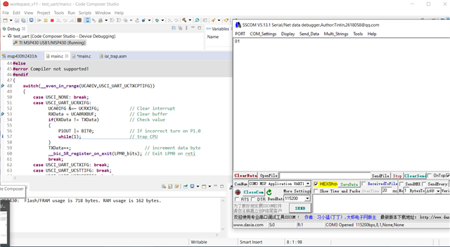
I tried putting a break at the switch case in the interrupt routine but it never triggers.

The code is mostly the same with the example here: dev.ti.com/.../node

Can anyone give me an advice?

Here is the code.

int main(void)
{
    WDTCTL = WDTPW | WDTHOLD;       // stop watchdog timer

    P1DIR = 0x01;
    P1OUT = 0x00;
    P1REN = 0x00;

    P2DIR &= ~BIT3;                 // Set P2.3 as in
    P2REN |= BIT3;                  // enable pull-up/down resistor
    P2OUT |= BIT3;                  // pull-up resistor
    P2IES |= BIT3;                  // enable interrupt

    P1SEL1 &= ~(BIT4 | BIT5);       // USCI_A0 UART operation
    P1SEL0 |= BIT4 | BIT5;

    UCA0CTLW0 |= UCSWRST;           // Put USCI_A0 to software reset
    UCA0CTLW0 |= UCSSEL__SMCLK;     // Use SMCLK(1048576Hz) for baud rate calculation
    UCA0BRW = 9;                    // N = f/BR = 1048576/115200 = 9
    UCA0MCTLW = 8;
    UCA0CTLW0 &= ~UCSWRST;          // Release USCI_A0 software reset
    UCA0IE |= UCRXIE;               // Enable USCI_A0 RX interrupt
    __bis_SR_register(GIE);
    //__bis_SR_register(LPM3_bits|GIE); //LPM3 not work when using SMCLK
    PM5CTL0 &= ~LOCKLPM5;           // Disable the GPIO power-on default high-impedance mode to activate previously configured port settings
    while(1);

}


#pragma vector=USCI_A0_VECTOR
__interrupt void USCI_A0_ISR(void)
{
    switch(__even_in_range(UCA0IV,USCI_UART_UCTXCPTIFG))
    {
    case USCI_NONE: break;
    case USCI_UART_UCRXIFG:
        P1OUT ^= 0x01;
        UCA0TXBUF = UCA0RXBUF;
        break;
    case USCI_UART_UCTXIFG: break;
    case USCI_UART_UCSTTIFG: break;
    case USCI_UART_UCTXCPTIFG: break;
    default: break;
  }
}

  • Hi,

    In this example code description "The device will wait in LPM0/LPM3 (based on clock source) until a UART character is received.". Have you send any data to the MCU to trigger the UART receive interrupt?

    If you do not have another device to send data through UART to your device, you can try this example code instead. https://dev.ti.com/tirex/explore/node?node=AC4fkny7IVqnhUvmZEUGSg__IOGqZri__LATEST

    It only needs to connect the TX pin to the RX pin.

    Best regards,

    Cash Hao

  • Hi Cash,

    Thank you for the response. My board is MSP-EXP430FR2433 and  I have sent some characters to USCI_A0 RX using Putty and sscom. Is this the correct way to trigger the interrupt?

    Or should I connect another UART device to P1.4 & P1.5?

  • Hi, 

    I am not familiar with this "Putty and sscom“. However, if you can not get a receive interrupt, I am supposing it is not a right way to trigger the device. You can try the example code me suggested on the former forum.  It does not need another device to trigger the interrupt. 

    Best regards,

    Cash Hao

  • Hi Cash,

    I have tried the example you mentioned above and it shows 01 in the serial monitor (sscom). Even there is something printed, Code Composer Studio cannot break at the switch case inside the __interrupt.

    Is this the expected result?

    (Edit typo)

  • I just tried your (original) code on an FR2433 Launchpad, and it acted as expected -- I got a (proper) echo, and the LED toggled. [Edit: I forgot to mention -- I reached the breakpoint as well.]

    It may be useful to go over your connections. Are all the jumpers installed on J101 (bridge header)? Is anything connected to the BoosterPack headers (J1/J2)?

    Also, keep in mind that with the debugger running the Backchannel UART acts slow/bursty. This doesn't affect the breakpoint behavior though.

  • Thank you for the help.

    Below is a picture of my board. All the jumpers are installed on J101.

    Also, I would like to ask which version of CCS are you using? I would like to give it a try.

  • Hi,

    You need to connect the P1.4 to the P1.5 with the example code I proposed. I am not seeing it in your picture.

    Best regards,

    Cash Hao

  • I was using CCSv9.3. (It's not obvious that that would have an effect, but who knows?)

    My connection to the Backchannel UART was via PuTTY (115200-8-N-1) and a Virtual COM (Win8.1). 

    Maybe it's useful to output something periodically to UCA0TXBUF ('U' looks good on a scope) in your while(1) in main. It doesn't help your Rx any, but it reassures that your OS isn't doing something funny with the port.

  • I have tried your suggestion which shorted the P1.4 and P1.4 (UART0 TX and RX).

    But neither anything had shown on the serial monitor nor the break-point was triggered

  • Thank you so much for the information.

    Same result when using CCS v9.3.

    If I change my while loop to something like this in the main loop. 'U' is printed in the serial monitor. But still the RX side is not working.

        while(1){
            UCA0TXBUF = 'U';
            P1OUT ^= 0x01;
            __delay_cycles(1048576);
        }

    Maybe I should borrow an oscilloscope and see what happen at the RX pin.

    Will update here if there is an update.

  • Hi,

    Sure. Use a oscilloscope will help us a lot to figure out what is happening on the RX pin. 

    Best regards,

    Cash Hao

  • Sorry for the late reply. I have got the oscilloscope and probe it to the RX UART pin of the board. But nothing is triggered when I send a byte to the serial terminal.

    And I have made a custom with a different model of MSP430 (MSP430FR5869) and using the same code to trigger the UART interrupt. The result is acted as expected. I can break at the interrupt routine and receive the echo I sent to the device. 

    Thank you all for your kind support and patience. 

**Attention** This is a public forum