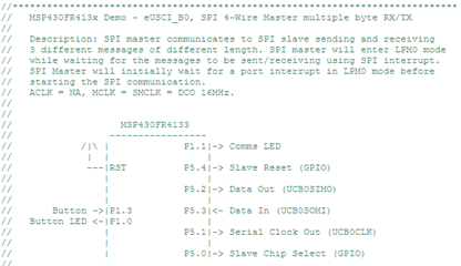
For a project we have been attempting to write a code for the MSP430fr4133 to behave as a master to the MFRC522 RFID reader which is our slave device to unlock a system if its ID is contained within an array of acceptable IDs which have access to unlock the system. We have been attempting to use SPI communication to connect the master and slave, but we haven't learned about this in class and so have been struggling with it heavily. I have managed to write some code based off a video I seen online, on a different controller which used eUSCI_A0, and configured it to use SPI in eUSCI_B0 on my controller. Using this code I have been able to tie together the MISO and MOSI pins and transmit simple data between the cables. For example setting up switch 1 to set the Tx buffer (UCB0TXBUF = 0x10) and switch 2 to set the Tx buffer (UCB0TXBUF = 0x66). Within the receive interrupt (ISR_EUSCI_B0) I have set the a variable Rx_data = UCB0RXBUF to then test the variable for the 0x10 and 0x66 to set different LEDs high when this data is detected. THIS IS ALL VISIBLEIN THE CODE BELOW
We are confused how to progress onwards from this. The mfrc522 data sheet claims we need to use the SDA/SS (not sure on the purpose of this pin), MISO, MOSI and the CLK pins for SPI mode. We don't know how we will transfer an RFID fob/ card ID over the RFID slave to the master as a string, as with the current setup it sends it as a single byte (I think) but for our case I think we may require 14 characters (which I also think is 14 bytes- not sure if my understanding on that is incorrect).
In our other program we have a method of comparing a string (which would be ID data read into the RxBuffer) and compare it to an array of strings of other IDs which may have unlock access. and so this works, our main priority is reading in the data from the slave.
#include <msp430.h>

int Rx_Data;

int main(void)
{
	WDTCTL = WDTPW | WDTHOLD;	    //stop watch-dog timer


	    //--Setup A0 SPI
            UCB0CTLW0 |= UCSWRST;       //Put B0 into software reset

            UCB0CTLW0 |= UCSSEL__SMCLK; //choose SMCLK ~= 16MHz
            UCB0BRW = 160;              //pre-scale=10 to set SCLK=100kHz

            UCB0CTLW0 |= UCSYNC;        //put into SPI mode
            UCB0CTLW0 |= UCMST;         //set as a master

        //-- Configure Ports
            P1DIR |= BIT5;              //Sets P1.5 to output to power MFRC522
            P1OUT |= BIT5;

            P1DIR |= BIT0;              //set P1.0 (red LED) to output
            P1OUT &= ~BIT0;             //LED1=OFF initially

            P4DIR |= BIT0;              //set P4.0 (green LED) to output
            P4OUT &= ~BIT0;             //LED2=OFF initially

            P1DIR &= ~BIT2;             //set P1.2 (SW1) to input
            P1REN |= BIT2;              //turn on resistor
            P1OUT |= BIT2;              //makes resistor pull-up-resistor
            P1IES |= BIT2;              //make sensitive to high-to-low

            P2DIR &= ~BIT6;             //set P2.6 (SW2) to input
            P2REN |= BIT6;              //turn on resistor
            P2OUT |= BIT6;              //makes resistor pull-up-resistor
            P2IES |= BIT6;              //make sensitive to high-to-low

            //P5SEL1 &= ~ BIT1;           //P5.1=SCLK (P1SEL1:P1SEL0 = 01)
            P5SEL0 |= BIT1;

            //P5SEL1 &= ~ BIT2;           //P5.2=SIMO (P5SEL1:P5SEL0 = 01)
            P5SEL0 |= BIT2;

            //P5SEL1 &= ~ BIT3;           //P5.3=SOMI (P5SEL1:P5SEL0 = 01)
            P5SEL0 |= BIT3;

            PM5CTL0 &= ~LOCKLPM5;       //turn on i/o

            UCB0CTLW0 &= ~UCSWRST;      //take B0 out of software reset

        //--Setup Interrupts
            P1IE |= BIT2;               //enable P1.2 IRQ (SW1)
            P1IFG &= ~BIT2;             //clear flag

            P2IE |= BIT6;               //enable P2.6 IRQ (SW1)
            P2IFG &= ~BIT6;             //clear flag

            UCB0IE |= UCRXIE;           //enable SPI Rx interrupt
            UCB0IFG &= ~UCRXIFG;        //clear flag

            __enable_interrupt();       //enable maskable interrupts

        while(1){}                      //do nothing

	return 0;

}


	//-------------------------------------------
	//--Interrupts
        #pragma vector = PORT1_VECTOR       //ISR for SW1
	    __interrupt void ISR_Port1_S1(void)
	    {
	        UCB0TXBUF = 0x10;               //Tx 0x10 out over SPI
	        P1IFG &= ~BIT2;                 //clear flag
	    }

        #pragma vector = PORT2_VECTOR       //ISR for SW2
        __interrupt void ISR_Port1_S2(void)
        {
            UCB0TXBUF = 0x66;               //Tx 0x66 out over SPI
            P2IFG &= ~BIT6;                 //clear flag
        }

        #pragma vector = USCI_B0_VECTOR    //DATA is in B0 SPI buffer
        __interrupt void ISR_EUSCI_B0(void)
        {
            Rx_Data = UCB0RXBUF;            //read Rx buffer

            if(Rx_Data == 0x10){
                P1OUT^= BIT0;               //Toggle LED 1
            }
            else if(Rx_Data == 0x66){
                P4OUT ^= BIT0;              //Toggle LED 2
            }
        }