This thread has been locked.

If you have a related question, please click the "Ask a related question" button in the top right corner. The newly created question will be automatically linked to this question.

MSP430F5342: Abnormal DCO drift exacerbated by LPM

Part Number: MSP430F5342

Hello everyone,

We are observing some unusual behavior in our system and are looking for the root cause. Our system is composed of an MSP430F5342 microcontroller with a 32kHz crystal on XT1, the DCO running at 20MHz, and the PMM core voltage set to level 2.

On initialization, we calibrate the DCO to 20MHz using the FLL with the 32kHz crystal as the source. This calibration is successful, after which we disable the FLL.

After disabling the FLL, however, the DCO begins a steady drift, reducing its frequency very rapidly. After about half an hour, the frequency drops to about 75% its original value. The crystal correctly remains at its nominal frequency.

The issue seems to be exacerbated by entering and exiting LPM0: the above drift is observed by waking up the microcontroller every second. If, instead, it wakes up every 50ms, the drift is much faster, dropping to 75% frequency in a few minutes.

The drop seems to be too fast to be explained by temperature shift. We do not observe drift this severe on our other systems, even in ones using the same microcontroller.

Leaving the FLL enabled fixes the issue. However, some of our systems cannot leave the FLL enabled constantly and are very timing-critical, so we are looking for a way to diagnose the root cause of this issue, or a way to prevent it on the first place.

Thanks in advance!

  • Hi Andreas,

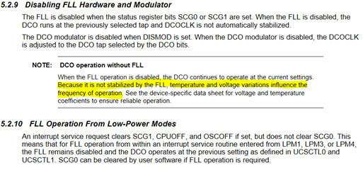
    In order to maintain a constant DCO frequency, the FLL is required to be enabled, else changes in temperature and voltage will directly impact the DCO output frequency.

    If you heat or cool the device and see the DCO frequency go up and down, then the effect you are seeing is due to temperature.

    I'll assume your application cannot leave the FLL enabled is due to power consumption, is this correct?

  • Hi Dennis,

    The main reason the application cannot leave the FLL enabled is that, while a small drift is acceptable, the jitter caused by a sudden change in frequency due to the FLL adjustment is not, even if the jitter is in the microsecond scale. I am not sure how much power the FLL consumes, but lower consumption is usually critical al well.

    The datasheet claims a 0.1%/°C drift, and a 1.9%/V drift. We are not seeing changes in temperature or voltage that would explain the 25% drop in frequency. It also does not explain why entering/exiting LPM0 worsens the effect. We run a few more tests and can confirm that without entering LPM0 there is no noticeable drift.

    Our applications usually check for a drift higher or lower than 5% of its nominal frequency and have run for years without triggering this check and without the FLL enabled, that is why a 25% drift is surprising to us. We also have not found any significant changes in hardware between the devices that present this problem and the devices that do not.

  • Hi Andres,

    Are these devices that are demonstrating the drift problem new MSP430F5432 in production or existing ones in the field?  If new, do you know if these were obtained through your normal distribution channel, or were these purchased differently?

    Can you provide a photo or date code marking from a good device and bad device?

    Also, I see you are operating at PMM core voltage level 2 at 20MHz, which should be ok, but I would be curious if you tried same experiment with core voltage level 3.

    What are you DCO settings?( UCSCTL0, UCSCTL1, UCSCTL2 and UCSCTL3)

  • Hi Andres,

    The datasheet claims a 0.1%/°C drift, and a 1.9%/V drift.

    As an experiment, can you try running your system @ 1MHz and see if same % drift compared @ 20MHz?

  • Hello Dennis,

    These are new devices, we have no evidence of devices on the field developing this problem after months/years in use.

    We tried the two things you suggested, increasing the core voltage to level 3, and lowering the DCO frequency (although to 10 MHz rather than 1MHz), without any observable improvement.

    I can get back to you this week with the datecode markings and the purchase method.

  • Hi Andres,

    Ok, good information and rules out those possibilities.   

  • Hi Andres,

    I have reached out to our test group to see, if by chance, they have relaxed the DCO test requirements that might explain why suddenly customer is seeing this behavior.

    We also have not found any significant changes in hardware between the devices that present this problem and the devices that do not.

    So is this a redesign of an existing product where they are seeing this issue? Would any of the changes be related to the MSP430?

  • The drift being associated with entry/exit from LPM0 would make me look at that code.

  • Hello everyone,

    The product is in fact a redesign of a previous product that did not present this issue.

    Some updates. We tried to run the code of the problematic device on another device with the same microcontroller that did not present the problem, and the issue appeared in the other device as well. So the problem does not appear to be related to a faulty unit or batch. It also does not point to a hardware design issue, since both devices have different hardware.

    We have simplified the code of both the problematic device and the other device to a minimum, and are now comparing differences. 

    The reduced code initializes the ports, the PMM, the clocks, and the timer, and toggles an output pin 10 times every 50 ms, going to LPM0 in between while waiting for a timer. The 50ms do not drift, since they are measured by a timer sourced by the crystal, but the time it takes to toggle the pin increases continuously on the problematic code.

    We are rerunning some tests. I suspect, like Dennis suggested, that the problem is related to the relationship between the core voltage and the DCO frequency.

    I will report back any findings.

  • Hi Andres,

    Thank you for the update. 

    Ok, this is helpful.  The timer should be periodic at 50ms due to its source, XT1 32KHz.  Can you post the portion of the code that toggles the GPIO.  I would think the code deterministic and shouldn't vary, unless you have other interrupts in the system that might introduce small delays?

    In addition to the increasing time to toggle the GPIO, if you measure the period (ON/OFF time) of one of the pulses, does it increase or stay the same?

  • Hello everyone,

    The observed effect was that the 50 ms were measured correctly, but the on/off time of each pulse increased overtime, due to one relying on the slow clock, and the other on the fast clock. The rising/falling time did not change, only the on/off time.

    We managed to find the root cause and fixed the issue. Due to some unintuitive handling of the SCG0 bit on the "backup/restore interrupt state" intrinsics and the "exit lpm" intrinsics of our compiler, we were enabling the FLL for a very short time every time we woke up from LMP0, only for a few CPU cycles. This time was so short that the FLL could not calibrate properly, and ended up modifying the DCO and MOD bits on UCSCTL0 with an undesired value.

    The time the FLL was left on was definitely shorter than the settling time defined on the user manual. Would you say this could be a possible effect of running the FLL for shorter than necessary?

    Thank you to you both!

**Attention** This is a public forum