This thread has been locked.

If you have a related question, please click the "Ask a related question" button in the top right corner. The newly created question will be automatically linked to this question.

EVM430-FR6043: "No connected HID devices" Ultrasonic Sensing Design Center (Water Mode)

Part Number: EVM430-FR6043
Other Parts Discussed in Thread: MSP430F5528, UNIFLASH

Hello,

I'm working on the "Optimized Ultrasonic Sensing Metrology Water Flow Measurement Reference Design" project on EVM430-FR6043. I built and ran the code on the board, but when I launch the  Ultrasonic Sensing Design Center Interface and try to connect it, I get the error: "No connected HID devices".

In principal, I configured jumpers correctly for Design Center communication (J1: 1-2 ON, 3-4: ON, 5-6: ON, 7-8: OFF and 9-10: OFF). Also, I configured jumpers so the board is powered by USB. The rest of jumpers haven't been touched since I bought the kit.

Thanks in advance,

Alberto

  • Hi Alberto,

    Has the EVM communicated with the GUI previously?

    It sounds like the HID bridge is not being detected.  There is a troubleshooting section in this document ( see section 7).

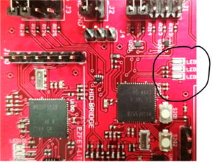
    There are also 3 LEDs next to the HID bridge.  I believe LED203 should be steady green (this is tells me the device has power) and LED202 toggles on/off once every second (this tells me the HID bridge is enumerated with Windows).

  • Hi Dennis,

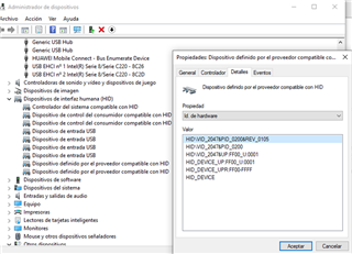
    Thanks for your answer. No, it's the first I'm trying to communicate the EVM with GUI. I checked the troubleshooting section you attached and Windows Device Manager recognise the HID bridge. I also reprogrammed the EVM but still get the same error.

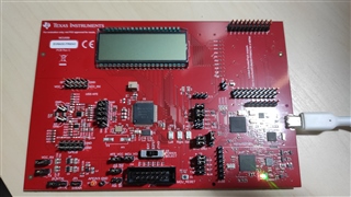
    The LED203 and LED202 you mentioned are turn off. In my case, LED102 is steady green as it's connected to USB and LED101 is red while I'm running the program.

    I didn't connect the transducers to the board yet because I first wanted to try the connection. I suppose that's not the probem, but just in case.


    I also tried removing jumper from J9, JP2, JP3, JP4, JP5, and J31 but still.

  • Hi Alberto,

    I see from your photo that LED 201 is not illuminated when the USB cable is attached - can you confirm?  If this is true, the it sounds like their is a problem with the MSP430F5528 HID Bridge MCU.  Normally, when it powers up, the MCU will turn on the LED to indicate power is good.  If not illuminated tells me the code is not running.  So you never see LED 201 turn on - correct?

  • Hi Dennis,

    Exactly, I've never seen LED201 turn on, only LED102 is green when USB cable is attached and LED101 is red while I'm running the code.

  • Hi Alberto,

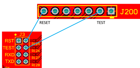
    Ok, this tells me the MSP430F5528 acting as the HID to serial bridge either not programmed or faulty.  I believe you can reprogram the device using the programmer that is on that same PCB.  Take a look at this picture.  You can remove the RESET and TEST jumpers and connect some wires as shown to the programming holes for the MSP430F5528 bridge. Attached is the firmware image for that device.  Use Uniflash to control the programming.  You can either download and install Uniflash, or you should be able to run it from the TI cloud.

    2844.TI_MSP_HIDBRIDGE__1_00_03_00__BANSHEE-USS-EVM.txt

  • Hi Dennis,

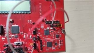
    I've connected the wires as image shown but UniFlash doesn't recognize the device. However, Windows Device Manager does.

    I checked the connections with schematics according to your image and JTAG_RESET is connected to GND and JTAG_TEST to HID-BRIDGE_RST, is it correct?

  • Hi Alberto,  from you photo it appears you have your jumper wires on the wrong side of J3.  I also see my earlier diagram was wrong on J200 as well. Here is connection diagram.

  • Hi Dennis, it works!!! Thank you a lot for you help.

**Attention** This is a public forum