This thread has been locked.

If you have a related question, please click the "Ask a related question" button in the top right corner. The newly created question will be automatically linked to this question.

MSP-EXP430FR5994: Setting UART baud rate

Part Number: MSP-EXP430FR5994

I need to set a 1Mbps uart baud rate with EUSCI_A0 or EUSCI_A1. Currently, I am using internal clocks on the EVM, the actual PCB will have external crystals. Is there a baud rate calculator for the FR series? It looks like I may need to set up over sampling in combination with Tables 30-4 and 30-5 from SLAU367P.

Thanks

  • Hi Priya,

    The link that Keith shared is the correct calculator for the DriverLib parameters.

    You can also check out the UART Lab in MSP Academy to see an example and explanation of how Baud Rate is set for the EUSCI_A0 Module at the register level. In the document you mentioned, Section 30.3.10 of the MSP430FR59xx Family User's Guide (SLAU367) explains the step-by-step process as well. 

    I'll also add here that the ez-Fet Debug Probe on the MSP-EXP430FR5994 launchpad is limited to 115.2k baud rate, so you would not be able to use the onboard UART backchannel with a 1Mbps UART. You would still be able to see any 1Mbps UART Traffic on the RXD and TXD pins if the baud rate is set correctly though. 

    Best Regards,
    Brandon Fisher

  • I'll also add here that the ez-Fet Debug Probe on the MSP-EXP430FR5994 launchpad is limited to 115.2k baud rate, so you would not be able to use the onboard UART backchannel with a 1Mbps UART.

    Never tested this, but as per eZ-FET firmware source, 256k is also supported.

    Prya, here is another BR calculator...

    4137.MSP430UartCalc.zip

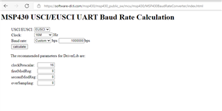
  • For SMCLK = 16MHz, the BR calculator shows the above values. What is the error rate for this setup?

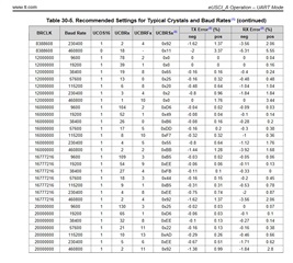
  • In the family guide linked above there is the following chart, as well as how to calculate the error:

  • /* --COPYRIGHT--,BSD
     * Copyright (c) 2017, Texas Instruments Incorporated
     * All rights reserved.
     *
     * Redistribution and use in source and binary forms, with or without
     * modification, are permitted provided that the following conditions
     * are met:
     *
     * *  Redistributions of source code must retain the above copyright
     *    notice, this list of conditions and the following disclaimer.
     *
     * *  Redistributions in binary form must reproduce the above copyright
     *    notice, this list of conditions and the following disclaimer in the
     *    documentation and/or other materials provided with the distribution.
     *
     * *  Neither the name of Texas Instruments Incorporated nor the names of
     *    its contributors may be used to endorse or promote products derived
     *    from this software without specific prior written permission.
     *
     * THIS SOFTWARE IS PROVIDED BY THE COPYRIGHT HOLDERS AND CONTRIBUTORS "AS IS"
     * AND ANY EXPRESS OR IMPLIED WARRANTIES, INCLUDING, BUT NOT LIMITED TO,
     * THE IMPLIED WARRANTIES OF MERCHANTABILITY AND FITNESS FOR A PARTICULAR
     * PURPOSE ARE DISCLAIMED. IN NO EVENT SHALL THE COPYRIGHT OWNER OR
     * CONTRIBUTORS BE LIABLE FOR ANY DIRECT, INDIRECT, INCIDENTAL, SPECIAL,
     * EXEMPLARY, OR CONSEQUENTIAL DAMAGES (INCLUDING, BUT NOT LIMITED TO,
     * PROCUREMENT OF SUBSTITUTE GOODS OR SERVICES; LOSS OF USE, DATA, OR PROFITS;
     * OR BUSINESS INTERRUPTION) HOWEVER CAUSED AND ON ANY THEORY OF LIABILITY,
     * WHETHER IN CONTRACT, STRICT LIABILITY, OR TORT (INCLUDING NEGLIGENCE OR
     * OTHERWISE) ARISING IN ANY WAY OUT OF THE USE OF THIS SOFTWARE,
     * EVEN IF ADVISED OF THE POSSIBILITY OF SUCH DAMAGE.
     * --/COPYRIGHT--*/
    //******************************************************************************
    //!  EUSCI_A1 External Loopback test using EUSCI_A_UART_init API
    //!
    //!  Description: This demo connects TX to RX of the MSP430 UART
    //!  The example code shows proper initialization of registers
    //!  and interrupts to receive and transmit data.
    //!
    //!  ACLK = BRCLK = 32.768kHz, MCLK = SMCLK = DCO = ~1MHz
    //!
    //!
    //!      Tested on MSP430FR5969
    //!             -----------------
    //!       RST -|     P2.0/UCA1TXD|----|
    //!            |                 |    |
    //!            |                 |    |
    //!            |     P2.1/UCA1RXD|----|
    //!            |                 |
    //!
    //! This example uses the following peripherals and I/O signals.  You must
    //! review these and change as needed for your own board:
    //! - UART peripheral
    //! - GPIO Port peripheral (for UART pins)
    //! - UCA1TXD
    //! - UCA1RXD
    //!
    //! This example uses the following interrupt handlers.  To use this example
    //! in your own application you must add these interrupt handlers to your
    //! vector table.
    //! - USCI_A1_VECTOR.
    //******************************************************************************
    #include "driverlib.h"
    
    uint16_t i;
    uint8_t RXData = 0, TXData = 0;
    uint8_t check = 0;
    
    void main(void)
    {
        // stop watchdog
        WDT_A_hold(WDT_A_BASE);
    
        // LFXT Setup
        //Set PJ.4 and PJ.5 as Primary Module Function Input.
        /*
    
        * Select Port J
        * Set Pin 4, 5 to input Primary Module Function, LFXT.
        */
        GPIO_setAsPeripheralModuleFunctionInputPin(
            GPIO_PORT_PJ,
            GPIO_PIN4 + GPIO_PIN5,
            GPIO_PRIMARY_MODULE_FUNCTION
        );
    
    
        // Set PJ.6 and PJ.7 as Primary Module Function Input, HFXT.
        GPIO_setAsPeripheralModuleFunctionInputPin(
               GPIO_PORT_PJ,
               GPIO_PIN6 + GPIO_PIN7,
               GPIO_PRIMARY_MODULE_FUNCTION
               );
    
        // Check if one FRAM waitstate is needed for 5962, 5994 device as well!
        FRAMCtl_A_configureWaitStateControl(FRAMCTL_A_ACCESS_TIME_CYCLES_1);
    
        uint32_t u32ClockFrequencyCheck = 0u;
        // Set DCO frequency to 8 MHz
    #ifdef DCO_CLK_SOURCES_MCLK
        CS_setDCOFreq(CS_DCORSEL_0, CS_DCOFSEL_6);
        //Set external clock frequency to 32.768 KHz
    
        CS_setExternalClockSource(32768, 0);
        CS_initClockSignal(CS_SMCLK, CS_DCOCLK_SELECT, CS_CLOCK_DIVIDER_1);
        CS_initClockSignal(CS_MCLK, CS_DCOCLK_SELECT, CS_CLOCK_DIVIDER_1);
    #else
    
        // JA - Enable lxft & HXFT
        CS_setExternalClockSource(32768, 16000000);
    
        CS_initClockSignal(CS_SMCLK, CS_HFXTCLK_SELECT, CS_CLOCK_DIVIDER_1);
        CS_initClockSignal(CS_MCLK, CS_HFXTCLK_SELECT, CS_CLOCK_DIVIDER_1);
    #endif //DCO_CLK_SOURCES_MCLK
        //Set ACLK=LFXT
        CS_initClockSignal(CS_ACLK, CS_LFXTCLK_SELECT, CS_CLOCK_DIVIDER_1);
    
    
        //Set the appropriate drive values for each oscillator for the launchpad vs. actual schematic.
    //    CS_turnOnLFXT(CS_LFXT_DRIVE_3);
          CS_turnOnLFXT(CS_LFXT_DRIVE_0);
    
        // JA
    #ifndef DCO_CLK_SOURCES_MCLK
        CS_turnOnHFXT(CS_HFXT_DRIVE_16MHZ_24MHZ);
    // JA - SMCLK appears to be running extremely slowly when sourced from HFXT
    
    #endif
          // JA - Check SMCLK, MCLK clock frequencies
          u32ClockFrequencyCheck = CS_getMCLK();
          u32ClockFrequencyCheck = CS_getSMCLK();


        // Configure UART pins
        //Set P2.0 and P2.1 as Secondary Module Function Input.
        /*
    
        * Select Port 2d
        * Set Pin 0, 1 to input Secondary Module Function, (UCA1TXD/UCA1SIMO, UCA1RXD/UCA1SOMI).
        */
        GPIO_setAsPeripheralModuleFunctionInputPin(
        GPIO_PORT_P2,
        GPIO_PIN5 + GPIO_PIN6,
        GPIO_SECONDARY_MODULE_FUNCTION
        );
    
        /*
         * Disable the GPIO power-on default high-impedance mode to activate
         * previously configured port settings
         */
        PMM_unlockLPM5();
    
        // Configure UART
        EUSCI_A_UART_initParam param = {0};
        param.selectClockSource = EUSCI_A_UART_CLOCKSOURCE_SMCLK;
        param.clockPrescalar = 16;
        param.firstModReg = 0;
        param.secondModReg = 0;
        param.parity = EUSCI_A_UART_NO_PARITY;
        param.msborLsbFirst = EUSCI_A_UART_LSB_FIRST;
        param.numberofStopBits = EUSCI_A_UART_ONE_STOP_BIT;
        param.uartMode = EUSCI_A_UART_MODE;
        param.overSampling = EUSCI_A_UART_LOW_FREQUENCY_BAUDRATE_GENERATION;
        
        if (STATUS_FAIL == EUSCI_A_UART_init(EUSCI_A1_BASE, &param)) {
            return;
        }
    
        EUSCI_A_UART_enable(EUSCI_A1_BASE);
    
        EUSCI_A_UART_clearInterrupt(EUSCI_A1_BASE,
          EUSCI_A_UART_RECEIVE_INTERRUPT);
    
        // Enable USCI_A1 RX interrupt
        EUSCI_A_UART_enableInterrupt(EUSCI_A1_BASE,
          EUSCI_A_UART_RECEIVE_INTERRUPT);                     // Enable interrupt
    
        __enable_interrupt();
        while (1)
        {
            TXData = TXData+1;                      // Increment TX data
            // Load data onto buffer
            EUSCI_A_UART_transmitData(EUSCI_A1_BASE,
            				   TXData);
            while(check != 1);
            check = 0;
        }
    }
    //******************************************************************************
    //
    //This is the USCI_A1 interrupt vector service routine.
    //
    //******************************************************************************
    #if defined(__TI_COMPILER_VERSION__) || defined(__IAR_SYSTEMS_ICC__)
    #pragma vector=USCI_A1_VECTOR
    __interrupt
    #elif defined(__GNUC__)
    __attribute__((interrupt(USCI_A1_VECTOR)))
    #endif
    void USCI_A1_ISR(void)
    {
      switch(__even_in_range(UCA1IV,USCI_UART_UCTXCPTIFG))
      {
        case USCI_NONE: break;
        case USCI_UART_UCRXIFG:
          RXData = EUSCI_A_UART_receiveData(EUSCI_A1_BASE);
          if(!(RXData == TXData))                   // Check value
          {
            while(1);
          }
          check =1;
          break;
        case USCI_UART_UCTXIFG: break;
        case USCI_UART_UCSTTIFG: break;
        case USCI_UART_UCTXCPTIFG: break;
      }
    }
    

    I am trying the driverlib uart example, modified for external crystals (high and low) and UART A1. I put in the uart baud rate parameters for EUSCI. I know the external clock is working, the u32ClockFrequencyCheck reads 16000000. 

    The UART is not working as it is currently setup. Any pointers appreciated. Thanks

  • Hi Priya,

    Your actual UART configuration seems okay to me. Just to confirm, when you say it is not working do you mean you are never seeing any UART data on pins 2.5 and 2.6 when they are tied together? 

    Is the code hanging anywhere when you run a debug session? 

    Best Regards,
    Brandon Fisher

  • /* --COPYRIGHT--,BSD
     * Copyright (c) 2017, Texas Instruments Incorporated
     * All rights reserved.
     *
     * Redistribution and use in source and binary forms, with or without
     * modification, are permitted provided that the following conditions
     * are met:
     *
     * *  Redistributions of source code must retain the above copyright
     *    notice, this list of conditions and the following disclaimer.
     *
     * *  Redistributions in binary form must reproduce the above copyright
     *    notice, this list of conditions and the following disclaimer in the
     *    documentation and/or other materials provided with the distribution.
     *
     * *  Neither the name of Texas Instruments Incorporated nor the names of
     *    its contributors may be used to endorse or promote products derived
     *    from this software without specific prior written permission.
     *
     * THIS SOFTWARE IS PROVIDED BY THE COPYRIGHT HOLDERS AND CONTRIBUTORS "AS IS"
     * AND ANY EXPRESS OR IMPLIED WARRANTIES, INCLUDING, BUT NOT LIMITED TO,
     * THE IMPLIED WARRANTIES OF MERCHANTABILITY AND FITNESS FOR A PARTICULAR
     * PURPOSE ARE DISCLAIMED. IN NO EVENT SHALL THE COPYRIGHT OWNER OR
     * CONTRIBUTORS BE LIABLE FOR ANY DIRECT, INDIRECT, INCIDENTAL, SPECIAL,
     * EXEMPLARY, OR CONSEQUENTIAL DAMAGES (INCLUDING, BUT NOT LIMITED TO,
     * PROCUREMENT OF SUBSTITUTE GOODS OR SERVICES; LOSS OF USE, DATA, OR PROFITS;
     * OR BUSINESS INTERRUPTION) HOWEVER CAUSED AND ON ANY THEORY OF LIABILITY,
     * WHETHER IN CONTRACT, STRICT LIABILITY, OR TORT (INCLUDING NEGLIGENCE OR
     * OTHERWISE) ARISING IN ANY WAY OUT OF THE USE OF THIS SOFTWARE,
     * EVEN IF ADVISED OF THE POSSIBILITY OF SUCH DAMAGE.
     * --/COPYRIGHT--*/
    //******************************************************************************
    //!  EUSCI_A1 External Loopback test using EUSCI_A_UART_init API
    //!
    //!  Description: This demo connects TX to RX of the MSP430 UART
    //!  The example code shows proper initialization of registers
    //!  and interrupts to receive and transmit data.
    //!
    //!  ACLK = BRCLK = 32.768kHz, MCLK = SMCLK = DCO = ~1MHz
    //!
    //!
    //!      Tested on MSP430FR5969
    //!             -----------------
    //!       RST -|     P2.0/UCA1TXD|----|
    //!            |                 |    |
    //!            |                 |    |
    //!            |     P2.1/UCA1RXD|----|
    //!            |                 |
    //!
    //! This example uses the following peripherals and I/O signals.  You must
    //! review these and change as needed for your own board:
    //! - UART peripheral
    //! - GPIO Port peripheral (for UART pins)
    //! - UCA1TXD
    //! - UCA1RXD
    //!
    //! This example uses the following interrupt handlers.  To use this example
    //! in your own application you must add these interrupt handlers to your
    //! vector table.
    //! - USCI_A1_VECTOR.
    //******************************************************************************
    #include "driverlib.h"
    
    uint16_t i;
    uint8_t RXData = 0, TXData = 0;
    uint8_t check = 0;
    
    void main(void)
    {
        uint32_t u32ClockFrequencyCheck = 0u;
        // stop watchdog
        WDT_A_hold(WDT_A_BASE);
        // Configure one FRAM waitstate as required by the device datasheet for MCLK
        // operation beyond 8MHz _before_ configuring the clock system.
        FRCTL0 = FRCTLPW | NWAITS_1;
    
        // Clock System Setup
        CSCTL0_H = CSKEY_H;                                     // Unlock CS registers
        CSCTL1 = DCOFSEL_0;                                     // Set DCO to 1MHz
    
        // Set SMCLK = MCLK = DCO, ACLK = VLOCLK
        CSCTL2 = SELA__VLOCLK | SELS__DCOCLK | SELM__DCOCLK;
    
        // Per Device Errata set divider to 4 before changing frequency to
        // prevent out of spec operation from overshoot transient
        CSCTL3 = DIVA__4 | DIVS__4 | DIVM__4;                   // Set all corresponding clk sources to divide by 4 for errata
        CSCTL1 = DCOFSEL_4 | DCORSEL;                           // Set DCO to 16MHz
    
        // Delay by ~10us to let DCO settle. 60 cycles = 20 cycles buffer + (10us / (1/4MHz))
        __delay_cycles(60);
        CSCTL3 = DIVA__1 | DIVS__1 | DIVM__1;                   // SMCLK=16Mhz MCLK=16MHz
        CSCTL0_H = 0;                                           // Lock CS registers


          // JA - Check SMCLK, MCLK clock frequencies
          u32ClockFrequencyCheck = CS_getMCLK();
          u32ClockFrequencyCheck = CS_getSMCLK();


        // Configure UART pins
        //Set P2.0 and P2.1 as Secondary Module Function Input.
        /*
    
        * Select Port 2d
        * Set Pin 0, 1 to input Secondary Module Function, (UCA1TXD/UCA1SIMO, UCA1RXD/UCA1SOMI).
        */
        GPIO_setAsPeripheralModuleFunctionInputPin(
        GPIO_PORT_P2,
        GPIO_PIN5 + GPIO_PIN6,
        GPIO_SECONDARY_MODULE_FUNCTION
        );
    
        /*
         * Disable the GPIO power-on default high-impedance mode to activate
         * previously configured port settings
         */
        PMM_unlockLPM5();
    
        // Configure UART
        EUSCI_A_UART_initParam param = {0};
        param.selectClockSource = EUSCI_A_UART_CLOCKSOURCE_SMCLK;
        param.clockPrescalar = 16;
        param.firstModReg = 0;
        param.secondModReg = 0;
        param.parity = EUSCI_A_UART_NO_PARITY;
        param.msborLsbFirst = EUSCI_A_UART_LSB_FIRST;
        param.numberofStopBits = EUSCI_A_UART_ONE_STOP_BIT;
        param.uartMode = EUSCI_A_UART_MODE;
        param.overSampling = EUSCI_A_UART_LOW_FREQUENCY_BAUDRATE_GENERATION;
        
        if (STATUS_FAIL == EUSCI_A_UART_init(EUSCI_A1_BASE, &param)) {
            return;
        }
    
        EUSCI_A_UART_enable(EUSCI_A1_BASE);
    
        EUSCI_A_UART_clearInterrupt(EUSCI_A1_BASE,
          EUSCI_A_UART_RECEIVE_INTERRUPT);
    
        // Enable USCI_A1 RX interrupt
        EUSCI_A_UART_enableInterrupt(EUSCI_A1_BASE,
          EUSCI_A_UART_RECEIVE_INTERRUPT);                     // Enable interrupt
    
        __enable_interrupt();
        while (1)
        {
            TXData = TXData+1;                      // Increment TX data
            // Load data onto buffer
            EUSCI_A_UART_transmitData(EUSCI_A1_BASE,
            				   TXData);
            while(check != 1);
            check = 0;
        }
    }
    //******************************************************************************
    //
    //This is the USCI_A1 interrupt vector service routine.
    //
    //******************************************************************************
    #if defined(__TI_COMPILER_VERSION__) || defined(__IAR_SYSTEMS_ICC__)
    #pragma vector=USCI_A1_VECTOR
    __interrupt
    #elif defined(__GNUC__)
    __attribute__((interrupt(USCI_A1_VECTOR)))
    #endif
    void USCI_A1_ISR(void)
    {
      switch(__even_in_range(UCA1IV,USCI_UART_UCTXCPTIFG))
      {
        case USCI_NONE: break;
        case USCI_UART_UCRXIFG:
          RXData = EUSCI_A_UART_receiveData(EUSCI_A1_BASE);
          if(!(RXData == TXData))                   // Check value
          {
            while(1);
          }
          check =1;
          break;
        case USCI_UART_UCTXIFG: break;
        case USCI_UART_UCSTTIFG: break;
        case USCI_UART_UCTXCPTIFG: break;
      }
    }
    

    Attached is the same example using DCO CLK, no external crystals. u32ClockFrequencyCheck is reading 16 MHz. For both clock versions all I see is a transition from low to high on the uart Tx line. Rx interrupt does not trigger.

  • Hi Priya,

    Here is a stripped down version of the Driverlib code that is currently working for me on the MSP-EXP430FR5994 at 1Mhz Baud Rate, using eUSCI_A1. Here I am using the internal DCO at 16Mhz. As far as I can tell the UART portions of these two code versions are identical, all I've done here is restore the clocking configuration to the original example code, and modified it for 16MHz BRCLK. 

    /* --COPYRIGHT--,BSD
     * Copyright (c) 2017, Texas Instruments Incorporated
     * All rights reserved.
     *
     * Redistribution and use in source and binary forms, with or without
     * modification, are permitted provided that the following conditions
     * are met:
     *
     * *  Redistributions of source code must retain the above copyright
     *    notice, this list of conditions and the following disclaimer.
     *
     * *  Redistributions in binary form must reproduce the above copyright
     *    notice, this list of conditions and the following disclaimer in the
     *    documentation and/or other materials provided with the distribution.
     *
     * *  Neither the name of Texas Instruments Incorporated nor the names of
     *    its contributors may be used to endorse or promote products derived
     *    from this software without specific prior written permission.
     *
     * THIS SOFTWARE IS PROVIDED BY THE COPYRIGHT HOLDERS AND CONTRIBUTORS "AS IS"
     * AND ANY EXPRESS OR IMPLIED WARRANTIES, INCLUDING, BUT NOT LIMITED TO,
     * THE IMPLIED WARRANTIES OF MERCHANTABILITY AND FITNESS FOR A PARTICULAR
     * PURPOSE ARE DISCLAIMED. IN NO EVENT SHALL THE COPYRIGHT OWNER OR
     * CONTRIBUTORS BE LIABLE FOR ANY DIRECT, INDIRECT, INCIDENTAL, SPECIAL,
     * EXEMPLARY, OR CONSEQUENTIAL DAMAGES (INCLUDING, BUT NOT LIMITED TO,
     * PROCUREMENT OF SUBSTITUTE GOODS OR SERVICES; LOSS OF USE, DATA, OR PROFITS;
     * OR BUSINESS INTERRUPTION) HOWEVER CAUSED AND ON ANY THEORY OF LIABILITY,
     * WHETHER IN CONTRACT, STRICT LIABILITY, OR TORT (INCLUDING NEGLIGENCE OR
     * OTHERWISE) ARISING IN ANY WAY OUT OF THE USE OF THIS SOFTWARE,
     * EVEN IF ADVISED OF THE POSSIBILITY OF SUCH DAMAGE.
     * --/COPYRIGHT--*/
    //******************************************************************************
    //!  EUSCI_A1 External Loopback test using EUSCI_A_UART_init API
    //!
    //!  Description: This demo connects TX to RX of the MSP430 UART
    //!  The example code shows proper initialization of registers
    //!  and interrupts to receive and transmit data.
    //!
    //!  ACLK = 32.768kHz, BRCLK = MCLK = SMCLK = DCO = ~16MHz
    //!
    //!
    //!      Tested on MSP430FR5994
    //!             -----------------
    //!       RST -|     P2.5/UCA1TXD|----|
    //!            |                 |    |
    //!            |                 |    |
    //!            |     P2.6/UCA1RXD|----|
    //!            |                 |
    //!
    //! This example uses the following peripherals and I/O signals.  You must
    //! review these and change as needed for your own board:
    //! - UART peripheral
    //! - GPIO Port peripheral (for UART pins)
    //! - UCA1TXD
    //! - UCA1RXD
    //!
    //! This example uses the following interrupt handlers.  To use this example
    //! in your own application you must add these interrupt handlers to your
    //! vector table.
    //! - USCI_A1_VECTOR.
    //******************************************************************************
    #include "driverlib.h"
    
    uint16_t i;
    uint8_t RXData = 0, TXData = 0;
    uint8_t check = 0;
    
    void main(void)
    {
        // stop watchdog
        WDT_A_hold(WDT_A_BASE);
    
        // LFXT Setup
        //Set PJ.4 and PJ.5 as Primary Module Function Input.
        /*
    
        * Select Port J
        * Set Pin 4, 5 to input Primary Module Function, LFXT.
        */
        GPIO_setAsPeripheralModuleFunctionInputPin(
            GPIO_PORT_PJ,
            GPIO_PIN4 + GPIO_PIN5,
            GPIO_PRIMARY_MODULE_FUNCTION
        );


        //Set DCO frequency to 16 MHz
    						   
        CS_setDCOFreq(CS_DCORSEL_1,CS_DCOFSEL_4);
        //Set external clock frequency to 32.768 KHz
    
        CS_setExternalClockSource(32768,0);


        //Set ACLK=LFXT
        CS_initClockSignal(CS_ACLK,CS_LFXTCLK_SELECT,CS_CLOCK_DIVIDER_1);
        //Set SMCLK = DCO with frequency divider of 1
        CS_initClockSignal(CS_SMCLK,CS_DCOCLK_SELECT,CS_CLOCK_DIVIDER_1);
        //Set MCLK = DCO with frequency divider of 1
        CS_initClockSignal(CS_MCLK,CS_DCOCLK_SELECT,CS_CLOCK_DIVIDER_1);
        //Start XT1 with no time out
        CS_turnOnLFXT(CS_LFXT_DRIVE_0);


        // Configure UART pins
        //Set P2.0 and P2.1 as Secondary Module Function Input.
        /*
    
        * Select Port 2d
        * Set Pin 5, 6 to input Secondary Module Function, (UCA1TXD/UCA1SIMO, UCA1RXD/UCA1SOMI).
        */
        GPIO_setAsPeripheralModuleFunctionInputPin(
        GPIO_PORT_P2,
        GPIO_PIN5 + GPIO_PIN6,
        GPIO_SECONDARY_MODULE_FUNCTION
        );
    
        /*
         * Disable the GPIO power-on default high-impedance mode to activate
         * previously configured port settings
         */
        PMM_unlockLPM5();
    
        // Configure UART
        EUSCI_A_UART_initParam param = {0};
        param.selectClockSource = EUSCI_A_UART_CLOCKSOURCE_SMCLK;
        param.clockPrescalar = 16;
        param.firstModReg = 0;
        param.secondModReg = 0;
        param.parity = EUSCI_A_UART_NO_PARITY;
        param.msborLsbFirst = EUSCI_A_UART_LSB_FIRST;
        param.numberofStopBits = EUSCI_A_UART_ONE_STOP_BIT;
        param.uartMode = EUSCI_A_UART_MODE;
        param.overSampling = EUSCI_A_UART_LOW_FREQUENCY_BAUDRATE_GENERATION;
        
        if (STATUS_FAIL == EUSCI_A_UART_init(EUSCI_A1_BASE, &param)) {
            return;
        }
    
        EUSCI_A_UART_enable(EUSCI_A1_BASE);
    
        EUSCI_A_UART_clearInterrupt(EUSCI_A1_BASE,
          EUSCI_A_UART_RECEIVE_INTERRUPT);
    
        // Enable USCI_A1 RX interrupt
        EUSCI_A_UART_enableInterrupt(EUSCI_A1_BASE,
          EUSCI_A_UART_RECEIVE_INTERRUPT);                     // Enable interrupt
    
        __enable_interrupt();
        while (1)
        {
            TXData = TXData+1;                      // Increment TX data
            // Load data onto buffer
            EUSCI_A_UART_transmitData(EUSCI_A1_BASE,
            				   TXData);
            while(check != 1);
            check = 0;
        }
    }
    //******************************************************************************
    //
    //This is the USCI_A1 interrupt vector service routine.
    //
    //******************************************************************************
    #if defined(__TI_COMPILER_VERSION__) || defined(__IAR_SYSTEMS_ICC__)
    #pragma vector=USCI_A1_VECTOR
    __interrupt
    #elif defined(__GNUC__)
    __attribute__((interrupt(USCI_A1_VECTOR)))
    #endif
    void USCI_A1_ISR(void)
    {
      switch(__even_in_range(UCA1IV,USCI_UART_UCTXCPTIFG))
      {
        case USCI_NONE: break;
        case USCI_UART_UCRXIFG:
          RXData = EUSCI_A_UART_receiveData(EUSCI_A1_BASE);
          if(!(RXData == TXData))                   // Check value
          {
            while(1);
          }
          check =1;
          break;
        case USCI_UART_UCTXIFG: break;
        case USCI_UART_UCSTTIFG: break;
        case USCI_UART_UCTXCPTIFG: break;
      }
    }
    

    I should point out that in the DriverLib code you shared you appear to be configuring the DCO for 8Mhz, and still using the UART settings based on a 16Mhz BRCLK. Even with that being the case, I would still expect to see some traffic on the UART channel, just at around 500kHz instead of 1MHz.

    Just so I understand your hardware setup a bit better, are you still using the Launchpad, and have pins 2.5 and 2.6 connected for loopback?  Have you installed a high frequency crystal on the launchpad in position Q2, or are you testing the external HFXT code on your own board? 

    Best Regards,
    Brandon Fisher

  •  I just realized a physical connection is needed for loopback. UART activity is as expected. I believe DCO CLK is set to 16MHz.

    CSCTL1 = DCOFSEL_4 | DCORSEL;                           // Set DCO to 16MHz

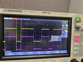
    I am seeing the baud rate is slightly off. With DCO clock, I get 980.4kHz bit clock. With external clock, I get 925.9 kHz. Its not exactly 1MHz. Why is this?

  • Hi Priya,

    Since the BRCLK is just being sourced from DCO or the external crystal, any error in higher frequency clock will show up in BRCLK.

    The DCO is just a variable RC Oscillator, and it is very likely that it is not operating exactly at 16MHz. The DCO is also being periodically corrected by the internal FLL. The way this is handled, it will on average generate a frequency around 16MHz, but at any instant it may be higher or lower than the target frequency. Variations in voltage and temperature can also cause changes in operating frequency. Table 8.12.3.3 of the device datasheet can give you an idea of the frequency error you can expected under different settings. 

    The error with the external oscillator does seem on the high side though. What oscillator are you using? It may have some specified frequency error, and that error can be made worse by layout or schematic issues. 

    Best Regards,
    Brandon Fisher

  • The allowed 16 MHz crystals have +/-50ppm tolerance. On the LP, this crystal was hand soldered which ay account for some errors. I played around with different drives and went back to my original one. A randomly checked bit is measuring at 1 MHz which is good enough for now. If there are problems later on, there maybe other ways to quantify accuracy. Thanks

**Attention** This is a public forum