Part Number: MSP430G2553
Hi, I use msp430g2553 for my project that implement on CCS, but I have some problems. I use the i2c protocol to communicate between MSP and vl53l5cx (ToF sensor of ST) - my i2c doesn't have interrupt. 2 timer interval are used WDT timer, TIMER0_A0 and 1 interrupt timer PORT2 with P2.0 pin.
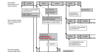
After a several time, it stuck on <while( (!(IFG2 & UCB0TXIFG))/> so I use time_out counter to continue, but it's still stuck, I think my code for init timer and interrupt is not good. Can you check for me?
/* I2C */
I2C_Mode I2C_Master_ReadReg(uint8_t dev_addr, uint16_t reg_addr, uint8_t *rxBuff, uint32_t count)
{
    /* Initialize state machine */
    i2cMasterMode = I2C_TX_REG_ADDRESS_MODE;
    i2cReceiveBuffer = rxBuff;
    isTransmitRegAddr = true;
    i2cTransmitRegAddr = reg_addr;
    i2cRXByteCtr = count;
    i2cTXByteCtr = 0;
    i2cReceiveIndex = 0;
    i2cTransmitIndex = 0;
    bool waitRx = true;
    uint8_t rx_val = 0;

    uint16_t i_timeout = 0; //minhnvk

    /* Initialize slave address and interrupts */
    UCB0I2CSA = dev_addr;
    IFG2 &= ~(UCB0TXIFG + UCB0RXIFG);       // Clear any pending interrupts

    UCB0CTL1 |= UCTR + UCTXSTT;             // I2C TX, start condition

    i_timeout = 0;
    while( (!(IFG2 & UCB0TXIFG)) && i_timeout <=65000) //minhnvk
    {
        i_timeout ++;
        if(i_timeout == 65000)
            return 99;
    }

    UCB0TXBUF = (i2cTransmitRegAddr & 0xFF00) >> 8;

    i_timeout = 0;
    while( (!(IFG2 & UCB0TXIFG)) && i_timeout <=65000)   //minhnvk
    {
        i_timeout ++;
        if(i_timeout == 65000)
           return 99;
    }

    UCB0TXBUF = (i2cTransmitRegAddr & 0xFF);

    i_timeout = 0;
    while( (!(IFG2 & UCB0TXIFG)) && i_timeout <=65000) //minhnvk
    {
        i_timeout ++;
        if(i_timeout == 65000)
           return 99;
    }

//    IE2 &= ~UCB0TXIE;              // Disable TX interrupt    //minhnvk cmt 7-4
    UCB0CTL1 &= ~UCTR;            // Switch to receiver
    UCB0CTL1 |= UCTXSTT;          // Send repeated start
    if (i2cRXByteCtr == 1)
    {
        //Must send stop since this is the N-1 byte
        i_timeout = 0;
        while((UCB0CTL1 & UCTXSTT) && i_timeout <= 65000)
        {
            i_timeout ++;
            if(i_timeout == 65000)
               return 99;
        }
        UCB0CTL1 |= UCTXSTP;      // Send stop condition
    }
    while(waitRx)
    {
        i_timeout = 0;
        while( (!(IFG2 & UCB0RXIFG)) && i_timeout <=65000)
        {
            i_timeout++;
            if(i_timeout == 65000)
               return 99;
        }

        {
            rx_val = UCB0RXBUF;
            if (i2cRXByteCtr)
            {
                i2cReceiveBuffer[i2cReceiveIndex++] = rx_val;
                i2cRXByteCtr--;
            }

            if (i2cRXByteCtr == 1)
            {
              UCB0CTL1 |= UCTXSTP;
            }
            else if (i2cRXByteCtr == 0)
            {
                IE2 &= ~UCB0RXIE; //minhnvk cmt   7-4
              i2cMasterMode = I2C_IDLE_MODE;
              waitRx = false;
            }
        }
    }

    return i2cMasterMode;

}


I2C_Mode I2C_Master_WriteReg(uint8_t dev_addr, uint16_t reg_addr, uint8_t *reg_data, uint32_t count)
{
    /* Initialize state machine */
    i2cMasterMode = I2C_TX_REG_ADDRESS_MODE;
    isTransmitRegAddr = true;
    i2cTransmitRegAddr = reg_addr;

    //Copy register data to TransmitBuffer
    i2cTransmitBuffer = reg_data;

    i2cTXByteCtr = count;
    i2cRXByteCtr = 0;
    i2cReceiveIndex = 0;
    i2cTransmitIndex = 0;
    bool waitTx = true;

    uint16_t i_timeout = 0; //minhnvk

    /* Initialize slave address and interrupts */
    UCB0I2CSA = dev_addr;
    IFG2 &= ~(UCB0TXIFG + UCB0RXIFG);       // Clear any pending interrupts

    UCB0CTL1 |= UCTR + UCTXSTT;             // I2C TX, start condition

    i_timeout = 0;
    while( (!(IFG2 & UCB0TXIFG)) && i_timeout <=65000) //minhnvk
    {
        i_timeout ++;
        if(i_timeout == 65000)
           return 99;
    }

    UCB0TXBUF = (i2cTransmitRegAddr & 0xFF00) >> 8;

    i_timeout = 0;
    while( (!(IFG2 & UCB0TXIFG)) && i_timeout <=65000) //minhnvk
    {
        i_timeout ++;
        if(i_timeout == 65000)
           return 99;
    }

    UCB0TXBUF = (i2cTransmitRegAddr & 0xFF);
    while(waitTx)
    {

        i_timeout = 0;
        while( (!(IFG2 & UCB0TXIFG)) && i_timeout <=65000) //minhnvk
        {
            i_timeout ++;
            if(i_timeout == 65000)
               return 99;
        }

        if (i2cTXByteCtr)
        {
            UCB0TXBUF = i2cTransmitBuffer[i2cTransmitIndex++];
            i2cTXByteCtr--;
        }
        else
        {
            //Done with transmission
            UCB0CTL1 |= UCTXSTP;     // Send stop condition
            i2cMasterMode = I2C_IDLE_MODE;
//            IE2 &= ~UCB0TXIE;                      // disable TX interrupt
            waitTx = false;
        }
    }


    return i2cMasterMode;
}
void initGPIOI2C()
{
//    P1DIR |= BIT0 + BIT1 + BIT2 + BIT3 + BIT4;
//    P1OUT &= ~(BIT0 + BIT1 + BIT2 + BIT3 + BIT4);


//    P2OUT &= ~BIT5;
//    P2OUT &= ~BIT2;
//    P2DIR |= BIT5 + BIT2;
//    P2OUT |= BIT5;
//    P2OUT &= ~BIT2;
//    __delay_cycles(1600000);
//    P2OUT &= ~BIT5;
//    P2OUT |= BIT2;//reset sensor slave

    P1OUT &= ~BIT0;
    P2OUT &= ~BIT2;
    P2DIR |= BIT2;
    P1DIR |= BIT0;
    P1OUT |= BIT0;
    P2OUT &= ~BIT2;
//    __delay_cycles(1600000);
    P1OUT &= ~BIT0;
    P2OUT |= BIT2;//reset sensor master

    P1SEL |= BIT6 + BIT7;                     // Assign I2C pins to USCI_B0
    P1SEL2|= BIT6 + BIT7;                     // Assign I2C pins to USCI_B0

}


void initI2C()
{
    UCB0CTL1 |= UCSWRST;                      // Enable SW reset
    UCB0CTL0 = UCMST + UCMODE_3 + UCSYNC;     // I2C Master, synchronous mode
    UCB0CTL1 = UCSSEL_2 + UCSWRST;            // Use SMCLK, keep SW reset
    UCB0BR0 = 40;                            // fSCL = SMCLK/160 = ~400kHz
    UCB0BR1 = 0;
    UCB0I2CSA = SLAVE_ADDR;                   // Slave Address
//    UCB0CTL1 &= ~UCSWRST;                     // Clear SW reset, resume operation
//    UCB0I2CIE |= UCNACKIE;
}
void I2Cinit(){

    initI2C();
    initGPIOI2C();
    UCB0CTL1 &= ~UCSWRST;
}

/* WDT timer and Timer0_A0 */
void setup_TimerA0(){
    BCSCTL1 = CALBC1_16MHZ;           // Set DCO to 1MHz
    DCOCTL =  CALDCO_16MHZ;
    WDTCTL = WDT_MDLY_8;             // Set Watchdog Timer interval to ~8ms
//    IE1 |= WDTIE;              // Enable WDT interrupt
    TA0CTL |= TASSEL_3 + MC_1;   //Interved TACLK, Continuous MODE
    TA0CCR0 = 10000;
    TA0CCTL0 = CCIE;
}
#pragma vector = TIMER0_A0_VECTOR
__interrupt void TimerInterruptCCR0(void){
    __disable_interrupt();
    count++;
//    processTimerEvent();
    if(StatusLed == FUZZY_LED)
    {
        counter++;
        if(counter == 5)
        {
            P2OUT &= ~BIT3;
            counter = 0;
        }
        else
            P2OUT |= BIT3;
    }
    __enable_interrupt();

}
/* Watchdog Timer interrupt service routine*/
#pragma vector=WDT_VECTOR
__interrupt void watchdog_timer(void)
{
    __disable_interrupt();
    if(TA0R < last_tc)
    {
        TempCnt = 0;
    }
    else
    {
        TempCnt = TA0R - last_tc;
    }
    if((GetMeasureTouch_delta() > Threshold))
        dem++;
    else
        dem = 0;
    if(dem > 5)
        buttonPress = true;
    else
        buttonPress = false;
    last_tc = TA0R;
    __enable_interrupt();
//    TA0CTL |= TACLR;            //Clear Timer_A TAR
}

/* PORT2 interrupt */
void initInterrupt(void)
{
    //slave to initiate transfer -
    P2DIR &= ~BIT0;                           // Set P2.0 to inpput direction
    P2REN |= BIT0;                            // Enable P2.0 internal resistance
    P2OUT |= BIT0;                            // Set P2.0 as pull-Up resistance
    P2IES |= BIT0;                            // P2.0 Hi/Lo edge
    P2IFG &= ~BIT0;                           // P2.0 IFG cleared
    P2IE |= BIT0;                             // P2.0 interrupt enabled
    InteruptState = FallingEdge;
}
#if defined(__TI_COMPILER_VERSION__) || defined(__IAR_SYSTEMS_ICC__)
#pragma vector=PORT2_VECTOR
__interrupt void Port_2(void)
#elif defined(__GNUC__)
void __attribute__ ((interrupt(PORT2_VECTOR))) Port_2 (void)
#else
#error Compiler not supported!
#endif
{
    __disable_interrupt();
     if(InteruptState == FallingEdge)
     {
         TimeInterupt = getTickCount();
         InteruptState = RisingEdge;

         P2IES &= ~BIT0;                            // P2.0 Hi/Lo edge
//         P2IE |= BIT0;                             // P2.0 interrupt enabled
         i =99;
     }
     else if (InteruptState == RisingEdge)
     {
         i = getTickCount() - TimeInterupt;

         P2IES |= BIT0;                            // P2.0 Hi/Lo edge
         InteruptState = FallingEdge;
     }
     switch(i)
     {
     case 1: case 2:
         StatusSlave = NONE_DETECT_SLAVE;
         break;

     case 3: case 4:
         StatusSlave = DETECT_SLAVE;
         break;

     case 5: case 6:
         slave_bright_level = slave_bright_high;
         break;

     case 7: case 8:
         StatusSlave = BTN_SLAVE;
         break;

     case 9: case 10:
         slave_bright_level = slave_bright_low;
         break;

     default:
         break;
     }
   P2IFG &= ~BIT0;                          // P2.0 IFG cleared
   P2IE |= BIT0;                             // P2.0 interrupt enabled
   __enable_interrupt();
}