This thread has been locked.

If you have a related question, please click the "Ask a related question" button in the top right corner. The newly created question will be automatically linked to this question.

MSP430FR2355: MSP430FR2355 SPI_Slave + I2C_Master Communication Error

Part Number: MSP430FR2355


Hi, everyone~

I don't live in an English-speaking country.

So, please understand even if the grammar is not correct:)

To begin with, I have difficulty developing SPI slave mode + I2C Master communication code.

My hardware infomation is as follows.

SPI_Master                        SPI_Slave / I2C_Master                  I2C_Slave

(SPC5748G)                         (MSP430FR2355)                     (IS31FL3xxxx)

-----------------------                   ------------------------                  ------------------------

        SIMO          |  -----------> |    SIMO (P1.2)   |                  |                           | 

        SCK            |  -----------> |    SCK   (P1.1)   |                  |                           | 

        GND           |  -----------> |    GND               |  -----------> |       GND             | 

        VCC           |  -----------> |     VCC               |  -----------> |       VCC             | 

                                                                           (4.7K Pull-up)

-----------------------                  |     SDA               |  -----------> |        SDA             

                                                                          (4.7K Pull-up)

                                              |     SCL               |  -----------> |        SCL             | 

                                               ------------------------                   ------------------------     

MSP430 operates in 3Pin-SPI Slave Mode (A1 Channel) and I2C Master Mode (B0 Channel) with no external crystals

I want to keep sending I2C Data to I2C_Slave(IS31FL3xxxx) while stacking SPI_Master's SPI Data into an array buffer called receiveData.

Currently, it has been confirmed that the operation is normal if only the SPI function and the I2C function are operated separately.

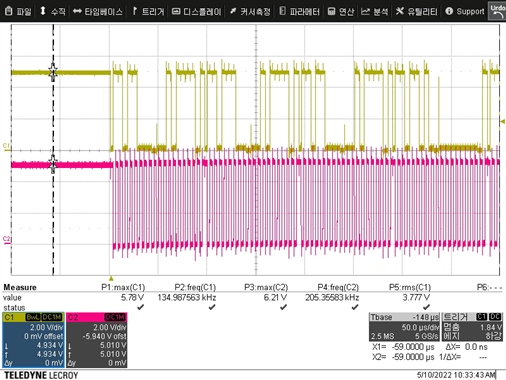
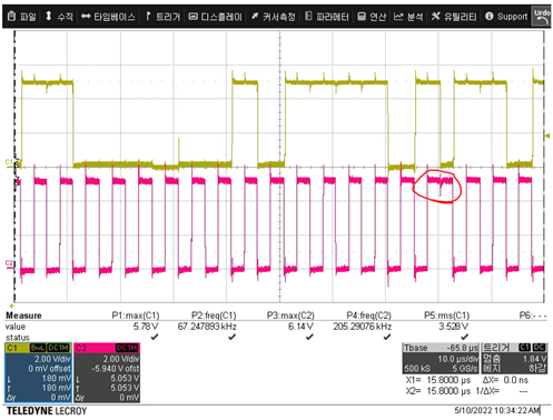
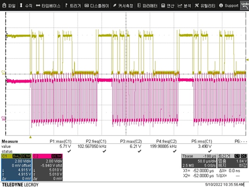
However, when the source code is combined to use both functions, I2C Communication normally, but SPI Communication fail.

When I check with the debugger, several SPI data sent by the SPI_Master are continuously lost.

By the way, if I erase the CS_initFLLSettle() function in the 135th line of the source code, SPI communication works normally again this time, and I2C communication fail.

I would appreciate it if you could give me advice on how to fix the source code

I'll leave my source code below for your check.

-----------------------------------------------------------------------------------------------

#include <msp430.h>
#include "driverlib.h"
#include "Board.h"
#include <string.h>
#include <stdio.h>
#include <stdlib.h>


//*****************************************************************************
//
// Slave LED Driver Address
//
//*****************************************************************************

#define LED_DRIVER_1 0xD8
#define LED_DRIVER_2 0xDA
#define LED_DRIVER_3 0xDC

//*****************************************************************************
//
//Target frequency for SMCLK in kHz
//
//*****************************************************************************

#define CS_SMCLK_DESIRED_FREQUENCY_IN_KHZ  1000
//*****************************************************************************
//
//SMCLK/FLLRef Ratio
//
//*****************************************************************************

#define CS_SMCLK_FLLREF_RATIO   30
//
//*****************************************************************************


void CLOCK_Init(void); // MSP430FR2355(No X-tal) clock initializing
void GPIO_Init(void); // GPIO initializing
void SPI_Init(void); // SPI initializing
void I2C_Init(void); // I2C initializing
void I2C_WRITE_DRIVER(uint8_t address, uint8_t Reg, uint8_t Data); // Command to LED Driver via I2C
void LED_ALL_Breathing(void); // ALL LED Breathing Test Code


uint8_t receiveData[200] = {0, };
uint8_t i2cdata_tx[2] = {0, };
uint8_t index = 0;
uint8_t TXByteCtr;


//*****************************************************************************

void CLOCK_Init(void)
{
    //Stop watchdog timer
    WDT_A_hold(WDT_A_BASE);

    FRCTL0 = FRCTLPW | NWAITS_2;

    __bis_SR_register(SCG0);                           // disable FLL
    CSCTL3 |= SELREF__REFOCLK;                         // Set REFO as FLL reference source
    CSCTL0 = 0;                                        // clear DCO and MOD registers
    CSCTL1 |= DCORSEL_7;                               // Set DCO = 24MHz
    CSCTL2 = FLLD_0 + 731;                             // DCOCLKDIV = 24MHz
    __delay_cycles(3);
    __bic_SR_register(SCG0);                           // enable FLL
    while(CSCTL7 & (FLLUNLOCK0 | FLLUNLOCK1));         // FLL locked

    CSCTL4 = SELMS__DCOCLKDIV | SELA__REFOCLK;

    PM5CTL0 &= ~LOCKLPM5;                        // Disable the GPIO power-on default high-impedance mode
                                                 // to activate previously configured port settings
}


void GPIO_Init(void)
{
    // Set P1.0 to output direction
    GPIO_setAsOutputPin(GPIO_PORT_P3, GPIO_PIN0);

    // Configure Pins for 3pin-SPI
    /*
    * Select Port 1
    * Set Pin 1, Pin 2 and Pin 3 to input with function.
    */
    GPIO_setAsPeripheralModuleFunctionInputPin(
        GPIO_PORT_P4,
        GPIO_PIN1 + GPIO_PIN2 + GPIO_PIN3,
        GPIO_PRIMARY_MODULE_FUNCTION
    );

    // Configure Pins for I2C
    GPIO_setAsPeripheralModuleFunctionInputPin(
        GPIO_PORT_UCB0SCL,
        GPIO_PIN_UCB0SCL,
        GPIO_FUNCTION_UCB0SCL
    );

    GPIO_setAsPeripheralModuleFunctionInputPin(
        GPIO_PORT_UCB0SDA,
        GPIO_PIN_UCB0SDA,
        GPIO_FUNCTION_UCB0SDA
    );
}


void SPI_Init(void)
{
    //Initialize slave to MSB first, inactive high clock polarity and 3 wire SPI
    EUSCI_A_SPI_initSlaveParam param = {0};
    param.msbFirst = EUSCI_A_SPI_MSB_FIRST;
    param.clockPhase = EUSCI_A_SPI_PHASE_DATA_CAPTURED_ONFIRST_CHANGED_ON_NEXT;
    param.clockPolarity = EUSCI_A_SPI_CLOCKPOLARITY_INACTIVITY_LOW;
    param.spiMode = EUSCI_A_SPI_3PIN;
    EUSCI_A_SPI_initSlave(EUSCI_A1_BASE, &param);

    //Enable SPI Module
    EUSCI_A_SPI_enable(EUSCI_A1_BASE);

    EUSCI_A_SPI_clearInterrupt(EUSCI_A1_BASE,
    EUSCI_A_SPI_RECEIVE_INTERRUPT
    );

    //Enable Receive interrupt
    EUSCI_A_SPI_enableInterrupt(EUSCI_A1_BASE,
    EUSCI_A_SPI_RECEIVE_INTERRUPT
    );

    __bis_SR_register(GIE); // enable interrupts
}


void I2C_Init(void)
{
    CS_initFLLSettle(
            CS_SMCLK_DESIRED_FREQUENCY_IN_KHZ,
            CS_SMCLK_FLLREF_RATIO
            );

    //Initialize Master
    EUSCI_B_I2C_initMasterParam param = {0};
    param.selectClockSource = EUSCI_B_I2C_CLOCKSOURCE_SMCLK;
    param.i2cClk = CS_getSMCLK();
    param.dataRate = EUSCI_B_I2C_SET_DATA_RATE_400KBPS;
    param.byteCounterThreshold = 0;
    param.autoSTOPGeneration = EUSCI_B_I2C_NO_AUTO_STOP;

    EUSCI_B_I2C_initMaster(EUSCI_B0_BASE, &param);

    //Set in transmit mode
    EUSCI_B_I2C_setMode(EUSCI_B0_BASE,
        EUSCI_B_I2C_TRANSMIT_MODE
        );

    //Enable I2C Module to start operations
    EUSCI_B_I2C_enable(EUSCI_B0_BASE);

    EUSCI_B_I2C_clearInterrupt(EUSCI_B0_BASE, EUSCI_B_I2C_TRANSMIT_INTERRUPT0);

    //Enable master Receive interrupt
    EUSCI_B_I2C_enableInterrupt(EUSCI_B0_BASE, EUSCI_B_I2C_TRANSMIT_INTERRUPT0);

    EUSCI_B_I2C_masterSendStart(EUSCI_B0_BASE);
}


void I2C_WRITE_DRIVER(uint8_t address, uint8_t Reg, uint8_t Data)
{
    TXByteCtr = 1;                          // Load TX byte counter

    i2cdata_tx[0] = Reg; // Select Register
    i2cdata_tx[1] = Data; // Command data

    EUSCI_B_I2C_setSlaveAddress(EUSCI_B0_BASE, address/2);

    while (EUSCI_B_I2C_SENDING_STOP == EUSCI_B_I2C_masterIsStopSent(EUSCI_B0_BASE));

    EUSCI_B_I2C_masterSendMultiByteStart(EUSCI_B0_BASE, i2cdata_tx[0]);
}


void LED_ALL_Breathing(void)
{
    int i, j, k, l;

    I2C_WRITE_DRIVER(LED_DRIVER_1,0x2F,0x00);//reset IC
    I2C_WRITE_DRIVER(LED_DRIVER_2,0x2F,0x00);//reset IC
    I2C_WRITE_DRIVER(LED_DRIVER_3,0x2F,0x00);//reset IC
    I2C_WRITE_DRIVER(LED_DRIVER_1,0x00,0x01);//Enable SSD
    I2C_WRITE_DRIVER(LED_DRIVER_2,0x00,0x01);//Enable SSD
    I2C_WRITE_DRIVER(LED_DRIVER_3,0x00,0x01);//Enable SSD

    for(i=0x14;i<=0x25;i++)
    {
        I2C_WRITE_DRIVER(LED_DRIVER_1,i,0x10);//enable all LED channel
        I2C_WRITE_DRIVER(LED_DRIVER_2,i,0x10);//enable all LED channel
        I2C_WRITE_DRIVER(LED_DRIVER_3,i,0x10);//enable all LED channel
    }
    I2C_WRITE_DRIVER(LED_DRIVER_1,0x26,0x00);//GCC
    I2C_WRITE_DRIVER(LED_DRIVER_2,0x26,0x00);//GCC
    I2C_WRITE_DRIVER(LED_DRIVER_3,0x26,0x00);//GCC
    I2C_WRITE_DRIVER(LED_DRIVER_1,0x27,0x00);//frequency
    I2C_WRITE_DRIVER(LED_DRIVER_2,0x27,0x00);//frequency
    I2C_WRITE_DRIVER(LED_DRIVER_3,0x27,0x00);//frequency

    for(j=0;j<=0xFF;j=j+8)
    {
      for(i=0x01;i<=0x12;i=i+1)
      {
          I2C_WRITE_DRIVER(LED_DRIVER_1,i,j);//write all channel PWM with 0x10
          I2C_WRITE_DRIVER(LED_DRIVER_2,i,j);//write all channel PWM with 0x10
          I2C_WRITE_DRIVER(LED_DRIVER_3,i,j);//write all channel PWM with 0x10
      }
      I2C_WRITE_DRIVER(LED_DRIVER_1,0x13,0x00);//update PWM and ON/OFF
      I2C_WRITE_DRIVER(LED_DRIVER_2,0x13,0x00);//update PWM and ON/OFF
      I2C_WRITE_DRIVER(LED_DRIVER_3,0x13,0x00);//update PWM and ON/OFF
    }

    for(l=0xFF;l>=0;l=l-8)
    {
      for(k=0x01;k<=0x12;k=k+1)
      {
          I2C_WRITE_DRIVER(LED_DRIVER_1,k,l);//write all channel PWM with 0x10
          I2C_WRITE_DRIVER(LED_DRIVER_2,k,l);//write all channel PWM with 0x10
          I2C_WRITE_DRIVER(LED_DRIVER_3,k,l);//write all channel PWM with 0x10
      }
      I2C_WRITE_DRIVER(LED_DRIVER_1,0x13,0x00);//update PWM and ON/OFF
      I2C_WRITE_DRIVER(LED_DRIVER_2,0x13,0x00);//update PWM and ON/OFF
      I2C_WRITE_DRIVER(LED_DRIVER_3,0x13,0x00);//update PWM and ON/OFF
    }
}


//*****************************************************************************


void main(void)
{
    CLOCK_Init();
    GPIO_Init();
    I2C_Init();
    SPI_Init();

    while(1)
    {
        LED_ALL_Breathing(); // infinite Breathing (fade in fade out)
    }
}


//******************************************************************************
//
//This is the USCI_B0 interrupt vector service routine.
//
//******************************************************************************
#if defined(__TI_COMPILER_VERSION__) || defined(__IAR_SYSTEMS_ICC__)
#pragma vector=USCI_A1_VECTOR
__interrupt
#elif defined(__GNUC__)
__attribute__((interrupt(USCI_B0_VECTOR)))
#endif
void USCI_A1_ISR (void)
{
    switch(__even_in_range(UCA1IV, USCI_SPI_UCTXIFG))
    {
        case USCI_SPI_UCRXIFG:      // UCRXIFG
            //USCI_A1 TX buffer ready?

             while (!EUSCI_A_SPI_getInterruptStatus(EUSCI_A1_BASE,
                       EUSCI_A_SPI_TRANSMIT_INTERRUPT
                        ));

            //Receive data from master
            receiveData[index] = EUSCI_A_SPI_receiveData(EUSCI_A1_BASE);

            index++;

            if(index >= 116)
            {
                index = 0;
            }

            break;
        default:
            break;
    }
}


//------------------------------------------------------------------------------
// The USCIAB0TX_ISR is structured such that it can be used to transmit any
// number of bytes by pre-loading TXByteCtr with the byte count. Also, TXData
// points to the next byte to transmit.
//------------------------------------------------------------------------------
#if defined(__TI_COMPILER_VERSION__) || defined(__IAR_SYSTEMS_ICC__)
#pragma vector=USCI_B0_VECTOR
__interrupt
#elif defined(__GNUC__)
__attribute__((interrupt(USCI_B0_VECTOR)))
#endif
void USCIB0_ISR(void)
{
    switch(__even_in_range(UCB0IV, USCI_I2C_UCBIT9IFG))
  {
        case USCI_NONE:             // No interrupts break;
            break;
        case USCI_I2C_UCALIFG:      // Arbitration lost
            break;
        case USCI_I2C_UCNACKIFG:    // NAK received (master only)
            //resend start if NACK
            //EUSCI_B_I2C_masterSendStart(EUSCI_B0_BASE);
            break;
        case USCI_I2C_UCTXIFG0:     // TXIFG0
            // Check TX byte counter
            if (TXByteCtr)
            {
                EUSCI_B_I2C_masterSendMultiByteNext(EUSCI_B0_BASE, i2cdata_tx[1]);

                // Decrement TX byte counter
                TXByteCtr--;
            }
            else
            {
                EUSCI_B_I2C_masterSendMultiByteStop(EUSCI_B0_BASE);

            }
            break;
        default:
            break;
  }
}

-----------------------------------------------------------------------------------------------

I’d be glad if you could help me.

Thanks.

  • Hi Kyung Won Seo,

    Do SPI and I2C transactions overlap? If so you may be dropping data because you are busy servicing an ISR. I notice that you have statements with while(condition) inside your ISR. This will increase the amount of time you are spending in the ISR and increase the chance that you may drop data.

    To get an idea of when the ISR is running, set a bit HIGH at the beginning of the ISR and then set it LOW right before the ISR returns. Assuming you have access to a logic analyzer or oscope, you can tell if there are overlaps. For example if you are servicing an I2C interrupt and you recieve 2 SPI transactions during that time it is likely that you will drop SPI data.

    It is always good practice to spend as little time as possible in the ISR. 

    Regards,

    Evan

  • Hi, Evan.

    Thank you for your reply.

    I modified the code so that SPI and I2C communication ISR do not overlap each other.

    #include <msp430.h>
    #include "driverlib.h"
    #include <string.h>
    #include <stdio.h>
    #include <stdlib.h>
    
    
    //*****************************************************************************
    //
    // Slave LED Driver Address
    //
    //*****************************************************************************
    
    #define LED_DRIVER_1 0xD8
    #define LED_DRIVER_2 0xDA
    #define LED_DRIVER_3 0xDC
    
    
    void CLOCK_Init(void); // MSP430FR2355(No X-tal) clock initializing
    void GPIO_Init(void); // GPIO initializing
    void SPI_Init(void); // SPI initializing
    void I2C_Init(void); // I2C initializing
    void I2C_WRITE_DRIVER(uint8_t address, uint8_t Reg, uint8_t Data); // Command to LED Driver via I2C
    void LED_ALL_ON(void); // ALL LED ON Test Code
    void LED_ALL_Breathing(void); // ALL LED Breathing Test Code
    
    
    uint8_t receiveData[200] = {0, };
    uint8_t i2cdata_tx[2] = {0, };
    uint8_t index = 0;
    uint8_t TXByteCtr;
    uint8_t spi_done = 0;


    //*****************************************************************************
    
    void CLOCK_Init(void)
    {
        FRCTL0 = FRCTLPW | NWAITS_1;
    
        WDTCTL = WDTPW | WDTHOLD;                         // disable watchdog
    
        __bis_SR_register(SCG0);                          // disable FLL
        CSCTL3 |= SELREF__REFOCLK;                        // Set REFO as FLL reference source
        CSCTL0 = 0;                                       // clear DCO and MOD registers
        CSCTL1 &= ~(DCORSEL_7);                           // Clear DCO frequency select bits first
        CSCTL5 |= DIVM__2;                                // Divide MCLK by 2 (8 MHz)
        CSCTL1 |= DCORSEL_5;                              // Set DCO = 16MHz
        CSCTL2 = FLLD_0 + 487;                            // DCOCLKDIV = 16MHz
        __delay_cycles(3);
        __bic_SR_register(SCG0);                          // enable FLL
        while(CSCTL7 & (FLLUNLOCK0 | FLLUNLOCK1));        // FLL locked
    
        CSCTL4 = SELMS__DCOCLKDIV | SELA__REFOCLK;        // set default REFO(~32768Hz) as ACLK source, ACLK = 32768Hz
                                                          // default DCOCLKDIV as MCLK and SMCLK source
        PM5CTL0 &= ~LOCKLPM5;                             // Disable the GPIO power-on default high-impedance mode
    
    }
    
    
    void GPIO_Init(void)
    {
        // Set P1.0 to output direction
        GPIO_setAsOutputPin(GPIO_PORT_P3, GPIO_PIN0);
    
        // Configure Pins for 3pin-SPI
        /*
        * Select Port 1
        * Set Pin 1, Pin 2 and Pin 3 to input with function.
        */
        GPIO_setAsPeripheralModuleFunctionInputPin(
            GPIO_PORT_P4,
            GPIO_PIN1 + GPIO_PIN2 + GPIO_PIN3,
            GPIO_PRIMARY_MODULE_FUNCTION
        );
    
        // Configure Pins for I2C
        GPIO_setAsPeripheralModuleFunctionInputPin(
            GPIO_PORT_P1,
            GPIO_PIN2 + GPIO_PIN3,
            GPIO_PRIMARY_MODULE_FUNCTION
        );
    }
    
    
    void SPI_Init(void)
    {
        //Configure USCI_A0 for SPI mode
        UCA1CTLW0 |= UCSWRST;                             // **Put state machine in reset**
                                                          // 3-pin, 8-bit SPI master
       // UCA1CTLW0 |= UCMST|UCSYNC|UCCKPH|UCMSB|UCMODE_0;
                                                          // Data valid first, clock high, MSB
        UCA1CTLW0 |= UCMST__SLAVE|UCSYNC|UCCKPH_H|UCCKPL__LOW|UCMSB|UCMODE_0;
    
    
        UCA1CTLW0 |= UCSSEL__SMCLK;                       // Select SMCLK
        UCA1BR0 = 0x08;                                   // BRCLK = SMCLK/8 = 1 MHz
        UCA1BR1 = 0;                                      //
        UCA1MCTLW = 0;                                    // No modulation
        UCA1CTLW0 &= ~UCSWRST;                            // **Initialize USCI state machine**
        UCA1IE |= UCRXIE;                                 // Enable USCI_A0 RX interrupt
    
    
        __bis_SR_register(GIE); // enable interrupts
    }
    
    
    void I2C_Init(void)
    {
        //Initialize Master
        EUSCI_B_I2C_initMasterParam param = {0};
        param.selectClockSource = EUSCI_B_I2C_CLOCKSOURCE_SMCLK;
        param.i2cClk = CS_getSMCLK();
        param.dataRate = EUSCI_B_I2C_SET_DATA_RATE_400KBPS;
        param.byteCounterThreshold = 0;
        param.autoSTOPGeneration = EUSCI_B_I2C_NO_AUTO_STOP;
    
        EUSCI_B_I2C_initMaster(EUSCI_B0_BASE, &param);
    
        //Set in transmit mode
        EUSCI_B_I2C_setMode(EUSCI_B0_BASE,
            EUSCI_B_I2C_TRANSMIT_MODE
            );
    
        //Enable I2C Module to start operations
        EUSCI_B_I2C_enable(EUSCI_B0_BASE);
    
        EUSCI_B_I2C_clearInterrupt(EUSCI_B0_BASE, EUSCI_B_I2C_TRANSMIT_INTERRUPT0);
    
        //Enable master Receive interrupt
        EUSCI_B_I2C_enableInterrupt(EUSCI_B0_BASE, EUSCI_B_I2C_TRANSMIT_INTERRUPT0);
    
        EUSCI_B_I2C_masterSendStart(EUSCI_B0_BASE);
    }
    
    
    void I2C_WRITE_DRIVER(uint8_t address, uint8_t Reg, uint8_t Data)
    {
        TXByteCtr = 1;                          // Load TX byte counter
    
        i2cdata_tx[0] = Reg; // Select Register
        i2cdata_tx[1] = Data; // Command data
    
        EUSCI_B_I2C_setSlaveAddress(EUSCI_B0_BASE, address/2);
    
        //while (EUSCI_B_I2C_SENDING_STOP == EUSCI_B_I2C_masterIsStopSent(EUSCI_B0_BASE));
        EUSCI_B_I2C_masterSendMultiByteStart(EUSCI_B0_BASE, i2cdata_tx[0]);
    }
    
    
    void LED_ALL_Breathing(void)
    {
        int i, j, k, l;
    
        I2C_WRITE_DRIVER(LED_DRIVER_1,0x2F,0x00);//reset IC
        I2C_WRITE_DRIVER(LED_DRIVER_2,0x2F,0x00);//reset IC
        I2C_WRITE_DRIVER(LED_DRIVER_3,0x2F,0x00);//reset IC
        I2C_WRITE_DRIVER(LED_DRIVER_1,0x00,0x01);//Enable SSD
        I2C_WRITE_DRIVER(LED_DRIVER_2,0x00,0x01);//Enable SSD
        I2C_WRITE_DRIVER(LED_DRIVER_3,0x00,0x01);//Enable SSD
    
        for(i=0x14;i<=0x25;i++)
        {
            I2C_WRITE_DRIVER(LED_DRIVER_1,i,0x10);//enable all LED channel
            I2C_WRITE_DRIVER(LED_DRIVER_2,i,0x10);//enable all LED channel
            I2C_WRITE_DRIVER(LED_DRIVER_3,i,0x10);//enable all LED channel
        }
        I2C_WRITE_DRIVER(LED_DRIVER_1,0x26,0x00);//GCC
        I2C_WRITE_DRIVER(LED_DRIVER_2,0x26,0x00);//GCC
        I2C_WRITE_DRIVER(LED_DRIVER_3,0x26,0x00);//GCC
        I2C_WRITE_DRIVER(LED_DRIVER_1,0x27,0x00);//frequency
        I2C_WRITE_DRIVER(LED_DRIVER_2,0x27,0x00);//frequency
        I2C_WRITE_DRIVER(LED_DRIVER_3,0x27,0x00);//frequency
    
        for(j=0;j<=0xFF;j=j+8)
        {
          for(i=0x01;i<=0x12;i=i+1)
          {
              I2C_WRITE_DRIVER(LED_DRIVER_1,i,j);//write all channel PWM with 0x10
              I2C_WRITE_DRIVER(LED_DRIVER_2,i,j);//write all channel PWM with 0x10
              I2C_WRITE_DRIVER(LED_DRIVER_3,i,j);//write all channel PWM with 0x10
          }
          I2C_WRITE_DRIVER(LED_DRIVER_1,0x13,0x00);//update PWM and ON/OFF
          I2C_WRITE_DRIVER(LED_DRIVER_2,0x13,0x00);//update PWM and ON/OFF
          I2C_WRITE_DRIVER(LED_DRIVER_3,0x13,0x00);//update PWM and ON/OFF
        }
    
        for(l=0xFF;l>=0;l=l-8)
        {
          for(k=0x01;k<=0x12;k=k+1)
          {
              I2C_WRITE_DRIVER(LED_DRIVER_1,k,l);//write all channel PWM with 0x10
              I2C_WRITE_DRIVER(LED_DRIVER_2,k,l);//write all channel PWM with 0x10
              I2C_WRITE_DRIVER(LED_DRIVER_3,k,l);//write all channel PWM with 0x10
          }
          I2C_WRITE_DRIVER(LED_DRIVER_1,0x13,0x00);//update PWM and ON/OFF
          I2C_WRITE_DRIVER(LED_DRIVER_2,0x13,0x00);//update PWM and ON/OFF
          I2C_WRITE_DRIVER(LED_DRIVER_3,0x13,0x00);//update PWM and ON/OFF
        }
    }
    
    
    void LED_ALL_ON(void)
    {
        int i;
    
        I2C_WRITE_DRIVER(LED_DRIVER_1,0x2F,0x00);//reset IC
        I2C_WRITE_DRIVER(LED_DRIVER_2,0x2F,0x00);//reset IC
        I2C_WRITE_DRIVER(LED_DRIVER_3,0x2F,0x00);//reset IC
        I2C_WRITE_DRIVER(LED_DRIVER_1,0x00,0x01);//Enable SSD
        I2C_WRITE_DRIVER(LED_DRIVER_2,0x00,0x01);//Enable SSD
        I2C_WRITE_DRIVER(LED_DRIVER_3,0x00,0x01);//Enable SSD
        for(i=0x14;i<=0x25;i++)
        {
            I2C_WRITE_DRIVER(LED_DRIVER_1,i,0x13);//enable all LED channel
            I2C_WRITE_DRIVER(LED_DRIVER_2,i,0x13);//enable all LED channel
            I2C_WRITE_DRIVER(LED_DRIVER_3,i,0x13);//enable all LED channel
        }
    
        I2C_WRITE_DRIVER(LED_DRIVER_1,0x26,0x00);//GCC
        I2C_WRITE_DRIVER(LED_DRIVER_2,0x26,0x00);//GCC
        I2C_WRITE_DRIVER(LED_DRIVER_3,0x26,0x00);//GCC
        I2C_WRITE_DRIVER(LED_DRIVER_1,0x27,0x00);//frequency
        I2C_WRITE_DRIVER(LED_DRIVER_2,0x27,0x00);//frequency
        I2C_WRITE_DRIVER(LED_DRIVER_3,0x27,0x00);//frequency
    
        for(i=0x01;i<=0x12;i=i+1)
        {
          I2C_WRITE_DRIVER(LED_DRIVER_1,i,0x64);//write all channel PWM with 0x10
          I2C_WRITE_DRIVER(LED_DRIVER_2,i,0x64);//write all channel PWM with 0x10
          I2C_WRITE_DRIVER(LED_DRIVER_3,i,0x64);//write all channel PWM with 0x10
        }
        I2C_WRITE_DRIVER(LED_DRIVER_1,0x13,0x00);//update PWM and ON/OFF
        I2C_WRITE_DRIVER(LED_DRIVER_2,0x13,0x00);//update PWM and ON/OFF
        I2C_WRITE_DRIVER(LED_DRIVER_3,0x13,0x00);//update PWM and ON/OFF
    }
    
    
    //*****************************************************************************
    
    
    void main(void)
    {
        CLOCK_Init();
        GPIO_Init();
        I2C_Init();
        SPI_Init();
        while(1)
        {
            if(spi_done)
            {
              //  LED_ALL_ON();
                LED_ALL_Breathing(); // infinite Breathing (fade in fade out)
                spi_done = 0;
                UCA1IE |= UCRXIE;
            }
    
        }
    }
    
    
    //******************************************************************************
    //
    //This is the USCI_B0 interrupt vector service routine.
    //
    //******************************************************************************
    #if defined(__TI_COMPILER_VERSION__) || defined(__IAR_SYSTEMS_ICC__)
    #pragma vector=USCI_A1_VECTOR
    __interrupt
    #elif defined(__GNUC__)
    __attribute__((interrupt(USCI_B0_VECTOR)))
    #endif
    void USCI_A1_ISR (void)
    {
        switch(__even_in_range(UCA1IV, USCI_SPI_UCTXIFG))
        {
            case USCI_SPI_UCRXIFG:      // UCRXIFG
    
                receiveData[index++] = UCA1RXBUF;          // Store received SPI data
    
                if(index >= 116)
                {
                    UCA1IE &= ~UCRXIE;
    
                    index = 0;
                    spi_done = 1;
                }
    
    
                break;
            default:
                break;
        }
    }
    
    
    //------------------------------------------------------------------------------
    // The USCIAB0TX_ISR is structured such that it can be used to transmit any
    // number of bytes by pre-loading TXByteCtr with the byte count. Also, TXData
    // points to the next byte to transmit.
    //------------------------------------------------------------------------------
    #if defined(__TI_COMPILER_VERSION__) || defined(__IAR_SYSTEMS_ICC__)
    #pragma vector=USCI_B0_VECTOR
    __interrupt
    #elif defined(__GNUC__)
    __attribute__((interrupt(USCI_B0_VECTOR)))
    #endif
    void USCIB0_ISR(void)
    {
        switch(__even_in_range(UCB0IV, USCI_I2C_UCBIT9IFG))
      {
            case USCI_NONE:             // No interrupts break;
                break;
            case USCI_I2C_UCALIFG:      // Arbitration lost
                break;
            case USCI_I2C_UCNACKIFG:    // NAK received (master only)
                //resend start if NACK
                //EUSCI_B_I2C_masterSendStart(EUSCI_B0_BASE);
                break;
            case USCI_I2C_UCTXIFG0:     // TXIFG0
                // Check TX byte counter
                if (TXByteCtr)
                {
                    EUSCI_B_I2C_masterSendMultiByteNext(EUSCI_B0_BASE, i2cdata_tx[1]);
    
                    // Decrement TX byte counter
                    TXByteCtr--;
                }
                else
                {
                    EUSCI_B_I2C_masterSendMultiByteStop(EUSCI_B0_BASE);
    
                }
                break;
            default:
                break;
      }
    }
    

    It still didn't work normally, so I took a waveform with an oscilloscope.

    It is measured that the SCL waveform periodically performs abnormal operation.

    Its enlargement is as follows.

    So I added code '__delay_cycles(1000);' after line 148th of the source code.

    Then, the SCL waveform changed like this.


    I downloaded the source code to my device and operated it, it seemed to work normally for some time.

    But after a while, an error occurred in my device.

    It's the waveform at that time.


    If I check with the debugger, the source code stuck in this location.

    Please help me solve this problem.

    thank you.

  • If the device is stuck on that line it is waiting for the UCTXIFG to be cleared. The fact that your I2C bus is pulled low means that someone is holding it low (idle state of I2c bus is high). Is the MSP or the secondary I2C device holding the bus low? 

    Evan

  • It was correct that I2C slave device was broken.
    Thank you so much Evan!

**Attention** This is a public forum