


Hello,
We want to use an external 32.768KHz crystal for the MSP430F6636 controller at XIN & XOUT pins and have the below queries.
1. Existing crystal ABS07W-32.768KHZ-J-1-T and define integrated effective load cap. 5.5pf by using XTS=0 and XCAPx=1 in the MCU datasheet. So, No need to connect the external load cap. Is our understanding correct?
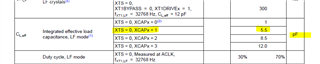
2. We want to define an alternate 32.768KHz crystal ABS06-32.768KHZ-T. If considered integrated effective load cap. 5.5pf by using XTS=0 and XCAPx=1. So, For XT1DRIVEx = 0, CL,eff ≤ 6 pF. (Pg. 29 MCU datasheet) then oscillation allowance (OA_LF) 210Kohm (Pg. 28 MCU datasheet).
Here crystal ESR value from the datasheet: 90Kohm. Safety factor = OA_LF/ESR = 2.33 (suitable qualification- SLAA322D) but drive level calculation value 2.87uW using below formula which is greater than 0.5uW crystal drive level . Should we add an external series resistor and the safety factor value looks OK?
| Drive_level =(ESR*((Pi*Fmax*C_tot)^2)*(Vpp^2))/2 |


Regards,
Ritul


 2. Please check the below values for used in this calculation.