This thread has been locked.

If you have a related question, please click the "Ask a related question" button in the top right corner. The newly created question will be automatically linked to this question.

MSP430FR59941: CryptoBSL entry sequence failure

Part Number: MSP430FR59941
Other Parts Discussed in Thread: UNIFLASH, MSP-FET, , MSP430FR5994

Hello,

We are having a problem with the CryptoBSL entry sequence not consistently functioning. 

The following sequence shows how to reproduce the issue:
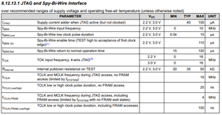
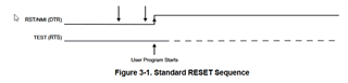
1) Standard Reset -- fails to reset MCU, 12us duration on RST
    Note: the time between resets was varied by 1 - 5 seconds
2) Standard Reset -- fails to reset MCU, 12us duration on RST
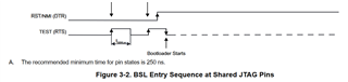
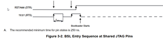
3) CryptoBSL Entry Sequence -- fails after polling 0x48 for 50ms (ACK failure)
4) Standard Reset -- success, 12us duration on RST
5) Standard Reset -- fails to reset MCU, 12us duration on RST
6) Standard Reset -- fails to reset MCU, 12us duration on RST
7) CryptoBSL Entry Sequence  -- success after polling 0x48 for 10ms
8) Standard Reset -- success, 12us duration on RST
9) Go to step 1
what we expect
1) Standard Reset -- success, 12us duration on RST
2) Standard Reset -- success, 12us duration on RST
3) CryptoBSL Entry Sequence  -- success after polling 0x48 for 10ms
4) Standard Reset -- success, 12us duration on RST
5) Go to step 1
One change that was made, was to increase the 12us duration on RST to 260us. Then all of the Standard Resets were functional, but sometimes the CryptoBSL Entry Sequence would still fail, and we were unable to get the CryptoBSL Entry Sequence to function until two more Standard Resets were issued.
The intent is to make the BSL Reset Sequence reliable.

Thank you so much in advance for you help with this!
  • Hi Tony,

    I have a couple of questions about your setup:

    • How are you resetting the device? Via software or hardware?
    • How to do you determine that the reset was unsuccessful?
    • How are you invoking CryptoBSL?

    Thanks,

    Evan

  • Hi Evan,

    Thanks for the quick reply!

    • How are you resetting the device? Via software or hardware?

    Hardware TEST & RST to initiate BSL Reset sequence.

    • How to do you determine that the reset was unsuccessful?

    For the BSL Reset sequence, we send address 0x48W for up to 50ms waiting for an ACK. If we receive an ACK, it takes around 10ms.
    In addition, for the Standard Reset sequence, we have an LED that we blink on every restart of the firmware code.

    • How are you invoking CryptoBSL?

    In order to exclude the extra complication of the CryptoBSL, we are experiencing the BSL Reset failure without setting the BSL signature to 0x5555. The ROM BSL is expected to be invoked. Sorry, I may have mislabeled this as specifically just a cryptobsl issue.

    Thanks,
    Tony

  • Hi Tony,

    I think it's strange that slowing down the reset pulse changes the behavior. Does your schematic/board match the reference schematic in figure 10-3 in the datasheet shown below? Specifically if you have too much capacitance on RST I could see that causing issues. 

    Can you review this and confirm your design meets these requirements?

    Thanks,

    Evan

  • Thanks Evan. I reached out to our partner company that did the design and I will update as soon as I hear back.

  • Hi Evan,

    From our partner company: We are not using JTAG to perform the reset sequence, we are controlling it from another device. C1 on our board is 1nF.

  • Hi Tony,

    Thanks for checking that out. Are you able to connect a oscilloscope to the RST and TEST pins to confirm that the pulse sequencing is correct? It should look like this:

    You will find more information in FRAM BSL user guide. I would also make sure the device is getting powered correctly.

    Regards,

    Evan

  • Hi Evan,

    I have attached the waveform showing what I believe to be the correct pattern (and hopefully the durations are within range).

  • Hi Tony,

    Thanks for the scope shot! I think you may be violating Tsbw,en (basically, the first pulse width). In the datasheet the max is 110us, but in your system it is marked as 120us. Can you reduce that and try again? Here is where I pulled the info from:

    FRAM BSL user guide:

    Datasheet table 8.12.13.1 JTAG and Spy-Bi-Wire Interface:

    Thanks,

    Evan

  • Hi Evan,

    Sorry for the slow response. We changed it to 100us and 110us and we still had the same result. 

  • This is the waveform for the standard reset (in case it is helpful).

  • Thanks for sharing that. 

    Why is the test pin toggling? It should be low during a normal reset:

    Regards,

    Evan

  • Even though the test pin is toggling, it is low during the reset, so shouldn't that be ok? Any thoughts on why does sending this TEST/RST sequence twice prevent the BSL reset from entering BSL mode?

  • Tony,

    Even thought test is low during reset it is transitioning near the reset edge. I'm not sure if that is causing you problems.

    Do you have access to an MSP FET or equivalent programmer? It might be easier to start from there and determine if you have any weird HW issues. If the MSP FET is able to program the device then I would take a look at what is different between the two reset/invoke sequences. If the MSP FET is having issues then I would take a closer look at the HW.

    Regards,

    Evan

  • Thanks Evan.

    Yes. We have not had an issue with the MSP FET. It seems to always work. We use it in spy-bi-wire mode.
    Is there a recommended way to reset the MSP430 when the BSL Reset fails to enter the BSL?

  • Tony,

    MSP FET can also do BSL. Would you be able to try that?

    Regards,

    Evan

  • We tried BSL Scripter and UNIFlash. Neither tool was able to perform a BSL reset through the MSP-FET. Neither tool is really an option, however.
    In deployment, we have an integrated device that is able to perform a BSL Reset to update the MSP firmware. We have observed that sometimes the MSP will consistently fail to enter the BSL. This is likely due to the SYSBSLIND failing to be set. We have discovered that performing those two standard resets is one way to put the MSP into this state where a BSL Reset sequence that previously worked as expected, now fails. The solution we are seeking is a recovery process that will reliably put the MSP back into a state where the BSL Reset will work as expected.

    Thanks,
    Tony

  • I understand that you can't use the MSP FET in production. I just wanted to see if you could use it to program the device at all, which you've reported you can't. Do you have a launchpad you could try? If you can program the LP thru BSL using the MSP FET then I would suspect something is wrong with your HW. 

    Evan

  • We have the MSP430FR5994 launchpad, but this board utilizes a UART BSL. The design we have uses an MSP430FR59941, which uses the I2C BSL. As a result we are not able to perform the requested test on a launchpad.
    We were able to connect the additional MSP-FET signals for TEST & RESET to the MSP430FR59941. We see UNIFlash toggling TEST and RESET to produce the BSL RESET waveform twice. Next we see the UNIFlash toggle I2C and send a 0x48W and a 0x48R. Both are NAKed. The MSP-FET does worse than the current hardware design. The current hardware design works most of the time, except for the situation described with the two RESET pulses.
    Another interesting tidbit, is that when the MSP is in this bad state where the BSL RESET does not enter the BSL, if we take pin 7, SBWTCK, from the MSP-FET and touch it to the MSP's TEST pin, a significant amount of noise on the TEST & RESET pins is generated and causes the MSP to reset and exit this bad state.
    Originally, the hardware design held TEST high until it needed to be toggled. This prevented the MSP-FET from being able to utilize the TEST pin. The TEST pin was changed to float when not in use. Could letting TEST float be part of the problem? Is there a better way to share this pin resource with the MSP-FET and our integrated device?

  • We have the MSP430FR5994 launchpad, but this board utilizes a UART BSL. The design we have uses an MSP430FR59941, which uses the I2C BSL. As a result we are not able to perform the requested test on a launchpad.

    Ok, understood.

    Another interesting tidbit, is that when the MSP is in this bad state where the BSL RESET does not enter the BSL, if we take pin 7, SBWTCK, from the MSP-FET and touch it to the MSP's TEST pin, a significant amount of noise on the TEST & RESET pins is generated and causes the MSP to reset and exit this bad state.

    How you powering the device when the MSP FET is connected? Are the devices sharing a common ground? I don't think connecting SBWTCK should generate a lot of noise. 

    Originally, the hardware design held TEST high until it needed to be toggled. This prevented the MSP-FET from being able to utilize the TEST pin. The TEST pin was changed to float when not in use. Could letting TEST float be part of the problem? Is there a better way to share this pin resource with the MSP-FET and our integrated device?

    The FRAM bootloader recommends using a pull-up and a cap to ground on TEST and TMS to avoid errantly entering JTAG mode. You said that you are normally holding TEST high which should be adequate unless your system is really noisy. How have you terminated TMS?

    I would check over the other reason BSL may fail to invoke listed in the FRAM BSL User's Guide too:

    Regards,

    Evan

  • How you powering the device when the MSP FET is connected?
        Separate power supply. The Vcc that is powering the MSP430 is connected to pin 4 VCC_TARGET

    Are the devices sharing a common ground?
        Yes.

    The FRAM bootloader recommends using a pull-up and a cap to ground on TEST and TMS to avoid errantly entering JTAG mode.
    If TCK and TMS are not connected to anything, would that cause an issue? We measured voltage on TCK and TMS, both were 0V. Are you thinking the device is entering JTAG mode? How do we exit JTAG mode? If we can exit JTAG tag mode, we could show that this is the issue.

    The document SLAU278AF: MSP430 Hardware Tools User Guide, specifies that TCK and TMS should be directly connected in 4-wire JTAG or no connection if in 2-wire JTAG (spy-bi-wire).
    See page 21, Figure 2-1. Signal Connections for 4-Wire JTAG Communication and page 23, Figure 2-3. Signal Connections for 2-Wire JTAG Communication (Spy-Bi-Wire) Used by All MSP430 SBW Capable
    Devices That are Not Part of F2xx, G2xx, F4xx Families
    These figures were also duplicated in the MSP430FR5994 user's guide.

    We had originally held TEST high, but we had to change it to float. When TEST was held high, the MSP-FET did not work.
    The MSP430 datasheet (slase54c) says this about TEST: This pin always has an internal pulldown enabled.
    Does this mean that TEST should not be able to float?
    Also, the BSL Reset failure state can be entered without having the MSP-FET connected to our device.

    We are reading slau320aj for more information about JTAG states. So far, it seems that having TEST float (open?) is normal behavior. If JTAG mode is an issue that is preventing the MSP430 from going into the BSL, is there a known way to exit this mode and have the BSL reliably work again?

    Thanks,

    Tony

  • Tony,

    Are you thinking the device is entering JTAG mode?

    I think this could explain the behavior that your are seeing.

    Based on the description of entry sequences in slau320aj.pdf holding TEST high will enable the SBW interface (see 2.3.1.1). Enabling the SBW will disable the BSL interface (see figure 2-13). 

    Can you try keeping TEST low during normal operation? Only toggle it when you intend to enter BSL mode.

    Regards,

    Evan

  • Can you try keeping TEST low during normal operation? Only toggle it when you intend to enter BSL mode.
    Yes, this is one of the things we will try. We also need to be able to allow the MSP-FET to activate the SBW/4-wire jtag modes as well. Is there a recommended way to arbitrate access to TEST?
  • Why do you need to have two devices simultaneously connected to test?

  • One is always connected, but has no debug capability. The other is the MSP-FET and we only connect it to debug.

  • If it's a debug board, a jumper is probably the easiest. If this is a production board as long as you can make the embedded programmer HiZ when you plug the MSPFET in, you should be ok.

  • Hi Evan,

    Sorry for the slow response, we were waiting on some test commands. We have found that the following waveform always works to ensure jtag mode is always disabled and BSL entry is granted.  Do you have any thoughts as to why this sequence would accomplish this?

    Thank you,
    -Tony

  • Hi Tony,

    That's interesting. I don't know why 3 pulses on TEST would make a difference.

    However, it seems like you system is still holding TEST high during normal operation. Is there something stopping you from holding TEST low? Setting test low is the expected operation condition for the device. If you are holding TEST high the SBW/JTAG interface will be enabled which I don't think makes sense for normal application operation and I think this is likely related to your issue. See 2.3.1.1 in Programming using JTAG interface:

    Regards,

    Evan

  • Hi Evan,

    We are waiting for a fw modification to keep TEST low and to send the described waveform. As soon as we can confirm that it works we should be good to close this issue. Thanks for your help! I will update ASAP.

    -Tony

**Attention** This is a public forum