This thread has been locked.

If you have a related question, please click the "Ask a related question" button in the top right corner. The newly created question will be automatically linked to this question.

EVM430-FR6047: Help on UART example code

Part Number: EVM430-FR6047


Hello there,

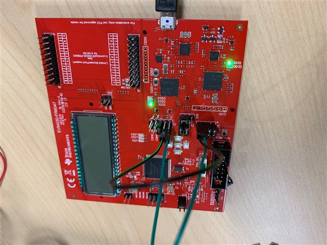
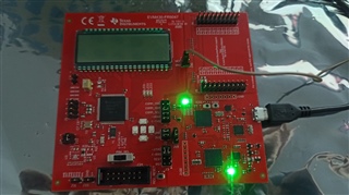
I'm using a EVM430FR6047 for water flow measurement on which I would like to introduce a LoRa module, so to configure it I would need a UART bridge from the USB to the UART on which the LoRa module would be installed.

Following this idea, I found the UART example codes for IAR Workbench, and specifically, I'm trying this one:
https://dev.ti.com/tirex/explore/node?node=APjcwJVdilmdY6x0OU7d.g__IOGqZri__LATEST&search=msp430fr6047

I'm doing this just to test out the configurations and to better understand the code and how everything works, and this would be really close to what would make sense to me, except that in this example, we would get an echo through the same UART.

And I have the following questions:

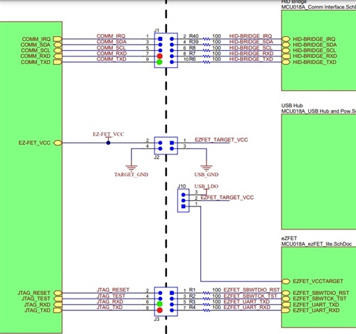
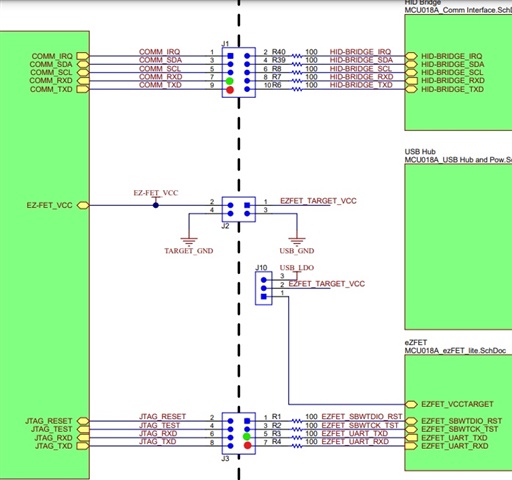
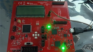
  1. Following the schematics slau138b the USB would be using the eUSCI_A0, with the pins comm_TXD and comm_RXD on P2.0 and P2.1 and those are the ones configured on the example code, yet the signal I'm getting is on JTAG_TXD and JTAG_RXD, on P1.2 and P1.3 which are eUSCI_A1. I'm testing it connected through USB and using the "Termite" terminal.
  2. Using the Termite terminal, if I rotate the jumpers to connect the TXD and RXD of UART 1, I'm getting and echo. Yet, if the jumpers are connected normally, the ->TXD pin does not have any voltage, yet the <-RXD is sending the message as I've observed in an oscilloscope. Images bellowing to better explain my point.

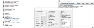
I'm testing it with the USB turned on, baudrate of 9600, debugger also on, so my question is, what am I doing wrong?

Thank you!

  • Hello,

    Can you try putting a jumper wire from JTAG_RXD (J3 block) to COMM_TXD (J1 block), and another jumper from JTAG_TXD (J3 block) to COMM_RXD (J1 block), and see if that gives you an echo?  I've attached a picture to illustrate, where I have color coded the locations to connect via jumper wires.

    Sincerely,

    Kyle

  • same happens, which is nothing. I realize that:

    COMM_RXD is polarized with 3.3v but does not receive
    COMM_TXD is polarized with 3.3v but does not transmit


    JTAG_RXD is polarized with 3.3v and does receive
    JTAG_TXD is not polarized and does not transmit

    So, if I shunt the JTAG UART, I get an echo, but otherwise, nothing at all...

  • Hi Carlos,

    I apologize for the delay. I am digging further into this issue, and will be able to provide a response tomorrow.

    Sincerely,

    Kyle Holub

  • I appreciate de effort whatever time it takes, so, thank you.

  • Hi Carlos,

    I just worked through your issue, and was able to get an echo.  Unfortunately, I had labeled the wrong pins to place a jumper across in the first picture I sent you.  I have attached a new schematic, and a picture of my board for you to look at for placing the jumper wires.  Let me know if placing these jumpers does not give you an echo.

    The issue was that the code you were exporting to the device was instantiating COMM_RXD and COMM_TXD, however the debugger does not communicate through HID-BRIDGE_RXD and HID_BRIDGE_TXD (bottom right of J1).  Rather, it communicates through EZFET pins (bottom right of J3 in the schematic).  Therefore, for the usage of UART on this board, you can use the jumpers as you see in the picture, or configure P1.2 and P1.3, and jumper across to the EZFET pins.  Let me know if you need any further explanation.

**Attention** This is a public forum