Part Number: MSP430FR2355
I'm given a 24-bit ADC and I'm trying to communicate through SPI on a MSP430FR2355 LaunchPad for my prototype. The operation is fairly straightforward:
Once a button press triggers an IRQ, the MCU's SIMO first sends a command byte (0b01000101) to the slave ADC input by writing to the MSP430's UCA0TXBUF register. In reply to the command byte, the ADC first outputs a status byte (0x17) to MCU's SOMI line, followed by a config byte 0x33 that gets repeatedly sent as long as I keep writing to the UCA0TXBUF (with a dummy byte) while keeping the STE line active (which I did manually on a GPIO). In my code, I send three dummy bytes following the command byte, and I expect to read the UCA0RXBUF in the following order
(1) write command byte (0x01000101) to UCA0TXBUF, read 0x17 in UCA0RXBUF and save in receive[0]
(2) write 1st dummy byte (0x00) to UCA0TXBUF, read 0x33 in UCA0RXBUF and save in receive[1]
(3) write 2nd dummy byte (0x00) to UCA0TXBUF, read 0x33 in UCA0RXBUF and save in receive[2]
(4) write 3rd dummy byte (0x00) to UCA0TXBUF, read 0x33 in UCA0RXBUF and save in receive[3]
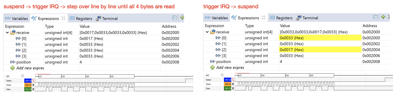
When I debug the program in CCS and step over line by line, I did get what I expect - variable array receive[4] = {0x17, 0x33, 0x33, 0x33}.
But if I let debug runs and arbitrarily suspend the program after the SPI event to read my buffered variable, I get receive[4] = {0x33, 0x33, 0x17, 0x33} <-- wrong order
I repeated several times and these results are consistent. I also monitored the SOMI with a mix-scope to make sure the ADC do indeed output {0x17, 0x33, 0x33, 0x33} in the order I expect - which it did. So I have no clue where I can go about troubleshooting this issue.
I hope someone can help explaining why this is happen or what should I try to troubleshoot this myself. Thank you,
#include <msp430.h>

char send[] =
{
    0b01000101,                 // command
    0x00, 0x00, 0x00            // dummy
};

unsigned int position;
unsigned int receive[4];

int main(void)
{
    WDTCTL = WDTPW | WDTHOLD;   // stop watchdog timer

    UCA0CTLW0 |= UCSWRST;       // put eUSCI_A0 into SW reset

    UCA0CTLW0 |= UCSSEL__SMCLK; // choose 1MHz SMCLK as BRCLK
    UCA0BRW = 10;               // 1MHz divide by 10 = 100kHz

    UCA0CTLW0 |= UCSYNC;        // set bit to SPI mode
    UCA0CTLW0 |= UCMST;         // set bit to SPI master mode
    UCA0CTLW0 |= UCMSB_1;       // UCMSB_0=LSB; UCMSB_1=MSB
    //UCA0CTLW0 |= UCMODE1;       // 0b10:4-pin with STE active LOW
    //UCA0CTLW0 &= ~UCMODE0;      // ..
    //UCA0CTLW0 |= UCSTEM;        // enable STE output pin
    UCA0CTLW0 &= ~UCMODE1;       // 0b00:3-pin SPI (handle P1.4 STE manually as a port)
    UCA0CTLW0 &= ~UCMODE0;
    UCA0CTLW0 &= ~UCSTEM;

    P1SEL1 &= ~BIT5;            // P1.5 (UCA0SCLK)
    P1SEL0 |= BIT5;             // P1.5 ..
    P1SEL1 &= ~BIT7;            // P1.7 (UCA0SIMO)
    P1SEL0 |= BIT7;             // P1.7 ..
    P1SEL1 &= ~BIT6;            // P1.6 (UCA0SOMI)
    P1SEL0 |= BIT6;             // P1.6 ..

    //P1SEL1 &= ~BIT4;            // P1.4 (STE)
    //P1SEL0 |= BIT4;             // P1.4 ..
    P1DIR |= BIT4;              // P1.4 set as output (manual STE)
    P1OUT |= BIT4;              // P1.4 stays HIGH by default (to be cleared LOW to initiate SPI)

    P4DIR &= ~BIT1;             // P4.1 (SW1) clear as input
    P4REN |= BIT1;              // P4.1 (SW1) enable pull-up/down resistance
    P4OUT |= BIT1;              // P4.1 (SW1) pull-up
    P4IES |= BIT1;              // P4.1 (SW) interrupt edge select: high-to-low transition

    PM5CTL0 &= ~LOCKLPM5;       // get out of LPM
    UCA0CTLW0 &= ~UCSWRST;      // get out of SW reset

    P4IFG &= ~BIT1;             // P4.1 (SW1) clear IFG
    P4IE |= BIT1;               // P4.1 (SW1) enable IRQ

    UCA0IFG &= ~UCTXIFG;        // clear SPI Tx IFG
    UCA0IE |= UCTXIE;           // enable SPI TX IRQ

    __enable_interrupt();

    while(1)
    {
        // do nothing
    }

    return 0;
}

#pragma vector = PORT4_VECTOR
__interrupt void ISR_Port4_S1(void)
{
    position = 0;
    P1OUT &= ~BIT4;             // P1.4 (manual STE) pull LOW to initiate SPI
    UCA0TXBUF = send[position];
    receive[0] = UCA0RXBUF;

    P4IFG &= ~BIT1;
}

#pragma vector = EUSCI_A0_VECTOR
__interrupt void ISR_EUSCI_A0(void)
{
    position++;
    if(position < sizeof(send))
    {
        UCA0TXBUF = send[position];
        receive[position] = UCA0RXBUF;
    }
    else
    {
        UCA0IFG &= ~UCTXIFG;

        // add delays to ensure last UCA0RXBUF is read before P1.4 (STE) is set HIGH
        // P1.4 (manual STE) set HIGH to stop SPI
        __delay_cycles(200);
        P1OUT |= BIT4;
    }
}