This thread has been locked.

If you have a related question, please click the "Ask a related question" button in the top right corner. The newly created question will be automatically linked to this question.

EVM430-FR6047: how to use the EVM430_FR6047 kit

Part Number: EVM430-FR6047
Other Parts Discussed in Thread: UNIFLASH,

1. To use the USS application of EVM430_FR6047, I uploaded a text file using Uniflash. (MSP430FR6047EVM_USS_Water_Demo_LPM_02_40_00_00, C:\ti\msp\UltrasonicWaterFR604x_02_40_00_00\image)
In the USS application, the board is connected, but LED3 turns red and does not work. I would like to know if there is a workaround. Also, I would like to know which pin(J8) the ultrasonic sensor is connected to

2. In addition, I would like to connect ADC and UART to test electromagnetic flow sensor on EVM430_FR6047. I would like to know which pin to connect to and which example to refer to.ultrasonic or electronic flow sensor connect

  • Hi CS,

    It sounds like you either don't have your transducers properly connected or you don't have the correct parameters configured in the GUI.

    The EVM430-FR6047 How to use guide, section 2.0 shows where to connect the transducers.  There are some basic configuration instructions located at this <link>.

    Also, check out the TIDM-1019 Water reference design document

  • Thank you for the reply.

    However, even if you change the settings by referring to the manual you gave, an error occurs.

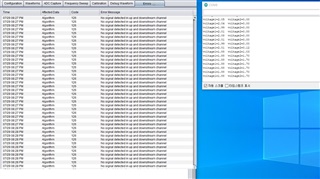
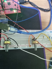
    To check the connection part of the ultrasonic sensor, ADC input test was performed as shown in the attached picture.
    As shown in the figure, two voltage values ​​are assumed to be the input values ​​of the ultrasonic sensor, and I want to check the status of ADC Capture for the two current voltage values, but the same error occurs. (CH0-voltage1, CH1-voltage2, GND-voltage ground)

    Is ADC test impossible on EVM board?
    Or do I have to do the ADC test in another method?

    Again, please provide the pin numbers and related examples to test the ADC operation.

  • Hi CS,

    Let's focus on getting the USS operating properly first.

    When you do an ADC capture in the GUI, do you see something like the capture below? The peak amplitude should be ~900 (ignore the 22% threshold in the picture for the moment). I just want see if your parameters are configured properly for your transducer and pipe so the ADC is capturing the waveform correctly.

    If you don't see a waveform similar to this, then the USS configuration parameters are not set correctly for your transducer/pipe. What transducer are you using?  What is their operating frequency, 1MHz, 2MHz, etc?

    I don't see a pipe (flow tube) in the picture.  Can you show what you are using. Do you have water in the tube with no air bubbles?

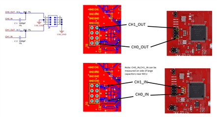
    Next, regarding your transducer connections, from the pictures you show it appears you have them wired correctly.  Here is a diagram:

    Regarding the ADC measurements, the SW is complicated and I honestly don't know the details to point you where to look.  Are you looking only for the ADC measurements?  Not absTOF, dTOF, flow rate, etc?

  • Thank you for answer. We are conducting EVM experiments for ultrasonic flow measurement and electromagnetic flow measurement.
    Question 1) I want to know if it is possible to connect to the EVM board to check the operation of the electromagnetic flowmeter (attached file). The technical documentation says to connect P1.0 or P1.1 to use ADC1, but the LED is connected to the EVM. I would like to know how to connect pins to simply read ADC values.
    
    Question 2) Please explain again in detail how to connect the ultrasonic sensor and how to connect it in the attached circuit diagram.

  • Hi Huron,

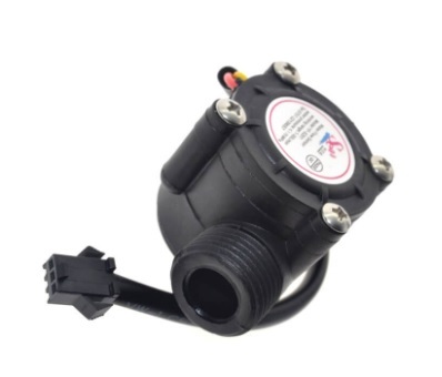
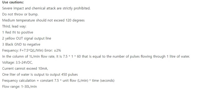
    You do realize that the picture you are showing is not an ultrasonic transducer.  It is a rotary pulse flow meter that generates a digital pulse train based on the speed of rotation caused by the water flow. This EVM is not designed to use this type of sensor.  You would typically use an MCU's Timer with capture/compare feature to measure this type of sensor.

  • Thank you for the reply.

    ENV430_FR6047 Can't do ADC test on board?

    I want to run the ADC example (msp430fr60x7_adc12_21) using the P1.1 pin on the ENV430_FR604 board.

    I want to know how to do it.

  • Hi huron,

    P1.1 on the EVM430-FR6047 is connected to a resistor and LED to ground, just so you know.

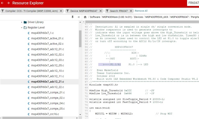
    There is an example using P1.1 located in the TI Resource Explorer. Have you tried it?

  • I'm trying to run the example(msp430fr60x7_adc12_01) you gave me, but I was wondering how to connect the pin(P1.1/A1) to the EVM430-FR6047. How do I connect the pin(P1.1/A1) to the  EVM430-FR6047 board?

  • Hi Huron,

    Here is graphic showing where to make convenient connection to P1.1/A1.  You must remove resistor first.

  • Hi Huron,

    It's been a couple of days since we have heard from you, so I'm going to assume you were able to move forward with your project.
    I will mark this posting as RESOLVED, but if this isn’t the case, please click the "This did NOT resolve my issue" button and reply to this thread with more information.
    If this thread is locked, please click the "Ask a related question" button, and in the new thread describe the current status of your issue and any additional details you may have to assist us in helping to solve your issues.

**Attention** This is a public forum