This thread has been locked.

If you have a related question, please click the "Ask a related question" button in the top right corner. The newly created question will be automatically linked to this question.

MSP430FR6889: Communicating over UART FTDI adaptor

Part Number: MSP430FR6889

Hello,

I am trying to write a program based on few information collected form different forum posts and some example codes. At this point I am able to directly send a ASCII value over UART but if I use the "printf" function nothing happens. At the end I want to send a few sensor data over UART. I would really appreciate it if someone can help me solve this issue. Here is my code:

#include <msp430.h>
#include "driverlib.h"
#include "NcApi.h"
#include "NeoParser.h"
#include "DSPLib.h"
#include <gpio.h>
#include <intrinsics.h> //
#include <stdint.h> //
#include <stdio.h> //


#define ENABLE_PINS     0xFFFE      // Required to use inputs and outputs
#define UART_CLK_SEL    0x0080      // Specifies accurate clock for UART peripheral
#define BR0_FOR_9600    0x34        // Value required to use 9600 baud
#define BR1_FOR_9600    0x00        // Value required to use 9600 baud
#define CLK_MOD         0x4911      // Microcontroller will "clean-up" clock signal
#define ACLK            0x0100      // Timer_A SMCLK source
#define UP              0x0010      // Timer_A UP mode

volatile int receiveData = 0;

void select_clock_signals(void);    // Assigns microcontroller clock signals
void assign_pins_to_uart(void);     // P4.2 is for TXD, P4.3 is for RXD
void use_9600_baud(void);           // UART operates at 9600 bits/second
void enable_TA0CTL(void);           // Enable the timer 0 counter
void set_timer0_count(int);

int main(void)
{
    WDTCTL = WDTPW | WDTHOLD;       // Stop WDT
    PM5CTL0 = ENABLE_PINS;          // Enable pins

    select_clock_signals();         // Assigns microcontroller clock signals
    assign_pins_to_uart();          // P4.2 is for TXD, P4.3 is for RXD
    use_9600_baud();                // UART operates at 9600 bits/second
    enable_TA0CTL();


    UCA0IE = UCRXIE;                // Enable RX interupt
    _BIS_SR(GIE);                   // Activate enabled UART RXD interrupt


    while(1)                      
    {
        static const int a=10;

            //UCA0TXBUF = 0x55;       // Send 0x55 out of P4.2
            printf("Reading samples\n");
            //printf("Reading samples %u\n",a);
    }
}

//*********************************************************************************
//* UART Interrupt Service Routine *
//* This is the ISR for both the TX interrupt and the RX interrupt *
//*********************************************************************************
#pragma vector=USCI_A0_VECTOR
__interrupt void UART_ISR(void)
{
    UCA0IFG = UCA0IFG & (~UCRXIFG); // Clear RX Interrupt FlaG
}
//*********************************************************************************
//* Select Clock Signals *
//*********************************************************************************
void select_clock_signals(void)
{
    CSCTL0 = 0xA500; // "Password" to access clock calibration registers
    CSCTL1 = 0x0046; // Specifies frequency of main clock
    CSCTL2 = 0x0133; // Assigns additional clock signals
    CSCTL3 = 0x0000; // Use clocks at intended frequency, do not slow them down
}
//*********************************************************************************
//* Used to Give UART Control of Appropriate Pins *
//*********************************************************************************
void assign_pins_to_uart(void)
{
    P4SEL1 = 0x00; // 0000 0000
    P4SEL0 = BIT3 | BIT2; // 0000 1100
    // ^^
    // ||
    // |+---- 01 assigns P4.2 to UART Transmit (TXD)
    // |
    // +----- 01 assigns P4.3 to UART Receive (RXD)
}
//*********************************************************************************
//* Specify UART Baud Rate *
//*********************************************************************************
void use_9600_baud(void)
{
    UCA0CTLW0 = UCSWRST; // Put UART into SoftWare ReSeT
    UCA0CTLW0 = UCA0CTLW0 | UART_CLK_SEL; // Specifies clock source for UART
    UCA0BR0 = BR0_FOR_9600; // Specifies bit rate (baud) of 9600
    UCA0BR1 = BR1_FOR_9600; // Specifies bit rate (baud) of 9600
    UCA0MCTLW = CLK_MOD; // "Cleans" clock signal
    UCA0CTLW0 = UCA0CTLW0 & (~UCSWRST); // Takes UART out of SoftWare ReSeT
}

void enable_TA0CTL(void)
{
    TA0CTL = ACLK | UP;             // Set ACLK, UP MODE
    TA0CCTL0 = CCIE;                // Enable interrupt for Timer_0
}
void set_timer0_count(int x)
{
    TA0CCR0 = x;                        //Used to set the timer0 counter
}

If I uncomment line 48 and 49 nothing shows up on the serial terminal. It only works when I uncomment line 47 and comment line 48 and 49.

Thanks. 

  • Hi Ifthekar, 

    Printf() will not output data over UART by default.

    If you comment out line 47, then here's no data being loaded to your UART TX Buffer, hence why you are not seeing any UART traffic unless that line is in place. In some other threads on the subject users have redirected the printf() output by overwriting the fputc() and fputs() functions.

    Edit: Just to add a link to our CCS documentation on using printf(): https://software-dl.ti.com/ccs/esd/documents/sdto_cgt_tips_for_using_printf.html


    Best Regards,
    Brandon Fisher

  • Hello Brandon,

    Thank you for your reply. I am not actually trying to send data to CCS over UART. I have configured P4.2 and P4.3 as UART TX/RX and I have connected a FTDI board to it and I am using the COM port of that FTDI board to read the UART data on a serial terminal like putty. 

    I have played around a bit after posting the issue and I wrote a short code to send the data over FTDI UART. It fixed half of my issues. Now I can send a string through it but I am unable to send intiger with it, for example ADC values collected from sensors. Here is the function:

    void UART_transmitString( char *pStr ) //Transmits a string over UART0
    {
        while( *pStr )
        {
            while(!(UCA0IFG&UCTXIFG));
            UCA0TXBUF = *pStr;
            pStr++;
        }
    }

    So if I comment line 47 and then replace the line 48 and 49 with these two lines:

               UART_transmitString("Reading samples\n");
               UART_transmitString("Reading samples %u\n", a);

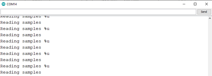
    I am continuously receiving these two lines in my serial terminal:


    So my UART communication is working. Obviously, as I have not implemented any function to send that integer "a" in that function, I am not receiving it. Do you have any suggestions on how to modify this function to send strings as well as integer, float, long, etc. values? 

    If I can make it work, then I won't have to use printf's at all.

    Thanks.

  • Hi Ifthekhar,

    You could look at the source code form the C standard library for vfprintf if you really wanted to recreate all the formatting functionality of printf: http://sourceware.org/git/?p=glibc.git;a=blob;f=stdio-common/vfprintf.c;h=fc370e8cbc4e9652a2ed377b1c6f2324f15b1bf9;hb=3321010338384ecdc6633a8b032bb0ed6aa9b19a

    If you want something simpler, you could start making progress here by just checking for the '%' character at *pStr and then look for your formatting flag at *(pStr + 1) so you know where to print your argument. 

    From there, you can find plenty of tutorials online on how to implement functions like itoa (converts int to string), which should help you with loading the int as chars to the transmit buffer for easier reading. 

    Best Regards,
    Brandon Fisher

  • Hi Brandon, thanks again. Finally, I got it working. I converted the numbers into strings. But now it looks like after sending every few bytes of data, the UART is taking a delay of 36 to 40 ms. I'm not sure why it's behaving this way. I am using a serial terminal to visualize the data. Any suggestions on fixing the issue?

    #include <msp430.h>
    #include "driverlib.h"
    #include <gpio.h>
    #include <intrinsics.h> //
    #include <stdint.h> //
    #include <stdio.h> //
    #include "stdarg.h"
    
    
    #define ENABLE_PINS     0xFFFE      // Required to use inputs and outputs
    #define UART_CLK_SEL    0x0080      // Specifies accurate clock for UART peripheral
    #define BR0_FOR_9600    0x34        // Value required to use 9600 baud
    #define BR1_FOR_9600    0x00        // Value required to use 9600 baud
    #define CLK_MOD         0x4911      // Microcontroller will "clean-up" clock signal
    #define ACLK            0x0100      // Timer_A SMCLK source
    #define UP              0x0010      // Timer_A UP mode
    
    volatile int receiveData = 0;
    
    void select_clock_signals(void);    // Assigns microcontroller clock signals
    void assign_pins_to_uart(void);     // P4.2 is for TXD, P4.3 is for RXD
    void use_9600_baud(void);           // UART operates at 9600 bits/second
    void enable_TA0CTL(void);           // Enable the timer 0 counter
    void set_timer0_count(int);
    void UART_transmitString();
    
    
    void print(char *text)
    {
        unsigned int i = 0;
        while(text[i] != '\0')
        {
            while (!(UCA0IFG&UCTXIFG));      // Check if TX is ongoing
            UCA0TXBUF = text[i];            // TX -> Received Char + 1
            i++;
        }
    }
    
    void printNumber(unsigned int num)
    {
        char buf[6];
        char *str = &buf[5];
    
        *str = '\0';
    
        do
        {
            unsigned long m = num;
            num /= 10;
            char c = (m - 10 * num) + '0';
            *--str = c;
        } while(num);
    
        print(str);
    }


    int main(void)
    {
        WDTCTL = WDTPW | WDTHOLD;       // Stop WDT
        PM5CTL0 = ENABLE_PINS;          // Enable pins
    
        select_clock_signals();         // Assigns microcontroller clock signals
        assign_pins_to_uart();          // P4.2 is for TXD, P4.3 is for RXD
        use_9600_baud();                // UART operates at 9600 bits/second
        enable_TA0CTL();
    
    
        UCA0IE = UCRXIE;                // Enable RX interupt
        _BIS_SR(GIE);                   // Activate enabled UART RXD interrupt
    
        while(1)                        // Wait here unless you get UART interrupt
        {
            static const int a= 115;
               printNumber(a);
               print("\r\n");
               //count++;
    
        }
    }
    
    //*********************************************************************************
    //* UART Interrupt Service Routine *
    //* This is the ISR for both the TX interrupt and the RX interrupt *
    //*********************************************************************************
    #pragma vector=USCI_A0_VECTOR
    __interrupt void USCI0TX_ISR(void)
    {
        UCA0IFG = UCA0IFG & (~UCRXIFG); // Clear RX Interrupt FlaG
    }
    //*********************************************************************************
    //* Select Clock Signals *
    //*********************************************************************************
    void select_clock_signals(void)
    {
        CSCTL0 = 0xA500; // "Password" to access clock calibration registers
        CSCTL1 = 0x0046; // Specifies frequency of main clock
        CSCTL2 = 0x0133; // Assigns additional clock signals
        CSCTL3 = 0x0000; // Use clocks at intended frequency, do not slow them down
    }
    //*********************************************************************************
    //* Used to Give UART Control of Appropriate Pins *
    //*********************************************************************************
    void assign_pins_to_uart(void)
    {
        P4SEL1 = 0x00; // 0000 0000
        P4SEL0 = BIT3 | BIT2; // 0000 1100
        //P4.2 to TXD
        //P4.3 toRXD
    }
    //*********************************************************************************
    //* Specify UART Baud Rate *
    //*********************************************************************************
    void use_9600_baud(void)
    {
        UCA0CTLW0 = UCSWRST; // Put UART into SoftWare ReSeT
        UCA0CTLW0 = UCA0CTLW0 | UART_CLK_SEL; // Specifies clock source for UART
        UCA0BR0 = BR0_FOR_9600; // Specifies bit rate (baud) of 9600
        UCA0BR1 = BR1_FOR_9600; // Specifies bit rate (baud) of 9600
        UCA0MCTLW = CLK_MOD; // "Cleans" clock signal
        UCA0CTLW0 = UCA0CTLW0 & (~UCSWRST); // Takes UART out of SoftWare ReSeT
    }
    
    void enable_TA0CTL(void)
    {
        TA0CTL = ACLK | UP;             // Set ACLK, UP MODE
        TA0CCTL0 = CCIE;                // Enable interrupt for Timer_0
    }
    void set_timer0_count(int x)
    {
        TA0CCR0 = x;                        //Used to set the timer0 counter
    }
    
    void UART_transmitString( char *pStr ) //Transmits a string over UART0
    {
        while( *pStr )
        {
            while(!(UCA0IFG&UCTXIFG));
            UCA0TXBUF = *pStr;
            pStr++;
        }
    }
    

  • Hi Ifthekhar,

    If you probe the UART lines with a scope or logic analyzer do you see this delay? 

    It is possible your serial terminal monitor is just reading the buffer every 30-40ms, and you are actually sending that data very regularly.

    Keep in mind that at 9600baud you are taking about 1ms to send a Char, or 5ms to send 5 chars ("115" plus your return and new line characters). Your terminal program's timestamps don't seem to reflect that. I think that 36-40ms is just how often it is updating. 

    Best Regards,
    Brandon Fisher 

  • Brandon hit the nail on the head. USB is not instantaneous and there are a lot of buffers between the hardware and the screen.

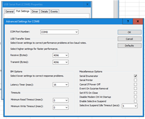
    If you have an FTDI chip, you can partially speed up the process. Open Device Manager, find and expand the "Ports (COM & LPT)" section, then double-click on your USB Serial Port entry which corresponds to your FTDI-UART adapter. Click the "Port Settings" tab in the "USB Serial Port (COMx) Properties" window, then click the "Advanced..." button near the bottom. Change the Latency Timer from 16 msec to a lower value, such as 8msec or less. After changing this value, unplug your adapter from USB then reconnect just for good measure.

    COM Port Advanced Settings

  • Hello Brandon,

    Thanks for the suggestion. You are correct. I have checked the UART Bus at the input of the FTDI adaptor with a logic analyzer and it looks like there is no such kind of delay. I am sending accelerometer data through UART to visualize it. I still have not found a popper UART or COM port scope that has a proper time domain based x-axis as well as markers. That's why I was using the serial terminal of the Arduino IDE. At least it has a time scale on the x-axis in milliseconds and if I freeze the screen I can do a rough calculation to verify the vibration frequency. However, I am currently receiving a 10x higher frequency value. For example, if the vibration frequency is 3 Hz, I am reading 30+-Hz. To me, it seems like the data transmission delay is the main reason. Is there any way I can reduce this delay?

    Thanks 

  • Hello Seth,

    Thanks for the suggestion. Sadly it did not solve the issue. I am receiving the same amount of delay. 

  • Hi Ifthekhar,

    If you want to reduce the UART communication delay you could increase your baud rate. Something like 115.2kBaud is a pretty standard value, and would give you a theoretical throughput more than 10x faster. So rather than taking about 1ms for a 10-byte transmission you would take 0.1ms. Most terminal programs would be able to support this rate as well.

    The of course wouldn't make your results appear on your terminal side without that 30-40ms window you are seeing, as that is system and resource dependent. 

    Best Regards,
    Brandon Fisher

  • Thanks, it looks like that the only option. 

**Attention** This is a public forum