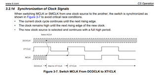
My project have to change MCLK form 1M to 38400 Hz and then receive (FLL reference clock is XT1)
My project try to LED ON/OFF with 1st failing edge, by used difference MCLK.
1. MCLK = 1 MHz, the LED work find.
2. Change MCLK to used XT1 oscillator (38400 Hz) the LED delay for 4 bit low. (see in picture)

Can I fix this delay problem?
My code:
int main(void)
{
WDTCTL = WDTPW | WDTHOLD; // stop watchdog timer
clock_setup(); // Configure DCO for 1MHz, which defaults to source the MCLK
PM5CTL0 &= ~LOCKLPM5; // Disable the GPIO power-on default high-impedance mode
//Configure P1.5 to interrupt input
P1DIR &= ~(BIT5); // Configure P1.5 as input direction pin
P1OUT |= BIT5; // Configure P1.5 as pulled-up
P1REN |= BIT5; // P1.5 pull-up register enable
P1IES |= BIT5; // P1.5 Hi--->Low edge
P1IFG &= ~(BIT5); // P1.5 IFG cleared
P1IE |= BIT5; // P1.5 interrupt enabled
P1SEL0 = BIT6 | BIT7; // UCA0 RXD and TXD P1.6/P1.7
P1DIR |= BIT0; // Set P1.0/LED to output direction
P1OUT &= ~BIT0; // P1.0 LED off
/* Configure UART
* 4800 baud at BRCLK = 38400 Hz
* UCOS16 = 0
* UCBRx = 8
* UCBRFx = 0
* UCBRSx = 0
*/
UCA0CTLW0 |= UCSWRST; // Hold UART module in reset mode
UCA0CTLW0 |= (UCPEN|UCPAR); // even parity
UCA0CTLW0 |= UCSSEL_1; // release from reset and set ACLK = 38400 as UCBRCLK
UCA0BRW = 8; // 38400/4800 - INT(38400/4800)= 8
UCA0MCTLW = 0x0000 ; // eUSCI_A0 Modulation Control Word Register: 38400/4800 - INT(38400/4800) = 0
// UCBRSx value = 0x00
UCA0CTLW0 &= ~UCSWRST; // Initialize eUSCI
UCA0IE |= UCRXIE; // Enable USCI_A0 RX interrupt
UCA0IE |= UCSTTIE; // Enable USCI_A0 Start bit (RX) interrupt
//some coding for LED on/of with mclk = 1 MHz
//test now work normally
/* Change mclk to xt1 (38400 Hz) */
CSCTL4 = SELMS__XT1CLK | SELA__XT1CLK; // set ACLK = XT1CLK = 38400Hz
UCA0IE &= ~UCTXIE; // Disable TX interrupt
UCA0IE &= ~UCRXIE; // Disable RX interrupt
UCA0IE &= ~UCSTTIE; // Start bit interrupt disble
for(;;){
__no_operation(); //for debug
}
}
#if defined(__TI_COMPILER_VERSION__) || defined(__IAR_SYSTEMS_ICC__)
#pragma vector=PORT1_VECTOR
__interrupt void Port_1(void)
#elif defined(__GNUC__)
void __attribute__ ((interrupt(PORT1_VECTOR))) Port_1 (void)
#else
#error Compiler not supported!
#endif
{
P1OUT ^= BIT0; // P1.0 LED toggle
P1IFG &= ~BIT5; // Clear P1.5 IFG
}
void clock_setup(){
P2SEL1 |= BIT6 | BIT7; // P2.6~P2.7: crystal pins
do
{
CSCTL7 &= ~(XT1OFFG | DCOFFG); // Clear XT1 and DCO fault flag
SFRIFG1 &= ~OFIFG;
}while (SFRIFG1 & OFIFG); // Test oscillator fault flag
_bis_SR_register(SCG0); // disable FLL
CSCTL3 |= SELREF__XT1CLK; // Set XT1 as FLL reference source
CSCTL1 = DCOFTRIMEN_1 | DCOFTRIM0 | DCOFTRIM1 | DCORSEL_0; // DCOFTRIM = 3, DCO Range = 1MHz
CSCTL2 = FLLD_0 + 25; // Set FLL to 1MHz
__delay_cycles(3); // Waiting time to stabilize
__bic_SR_register(SCG0); // enable FLL
Software_Trim(); // Software Trim to get the best DCOFTRIM value
CSCTL4 = SELMS__DCOCLKDIV | SELA__XT1CLK; // set ACLK = XT1CLK = 38400 Hz
// Default: DCOCLK = MCLK and SMCLK source
// Now that osc is running enable fault interrupt
SFRIE1 |= OFIE; // DCOCLK = MCLK and SMCLK source
}