This thread has been locked.
If you have a related question, please click the "Ask a related question" button in the top right corner. The newly created question will be automatically linked to this question.
Hi TI!
I am developing a power monitor and have seen the application reports for the MSP430I2040 (SLAA638) and the MSP430F6736 (slaa517).
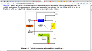
In the application report: 'Implementation of a Single-Phase Electronic Watt-Hour Single-Phase using the MSP430F6736(A)' (slaa517f), Figure 2.1, Page 3. Attached is the image.
In my design GND is NEUTRAL. The current sensor is a small value resistor connected to LIVE, as shown in the picture.
I think the MCU is broken with the schematic shown in the picture. Because the LIVE (120/230 VAC) will be connected to the ADC of the MCU.
Am I right? The MCU is broken?
Hello,
If the LIVE connection (120/230 VAC) was directly connected to a pin of the device, yes it is broken. You might have even seen some smoke come out of it.
A current transformer (CT) or shunt should be used to measure the current. I recommend taking a look at the full design guide here. In section 4.1, it mentions that the current inputs should not exceed 920mV.
Thank you
Tim Claycomb
Sincerely, thank you very much!
My problem is that I need to sense current in the live, because it is for a three phase system. I need to sense the current in each live.
Honestly I would like to use the current sensing resistor option.
As an alternative I have the idea of changing the polarity at the input of the power supply. Then the gnd of the MSP430 will be the live and I can put the sense resistor. Then I would need three power supplies and three MCUs. I show the idea in a picture.
1-) Does the idea described above and shown in the picture make sense?
2-) In case of the CT, could you please suggest me some commercial CT?
3-) I think it is not a common component. Am I wrong?
Hi,
1-) Does the idea described above and shown in the picture make sense?
What you've drawn is a simple shunt configuration, which could work. However it is lacking any protection. It will be up to you to determine the best method to get current readings in your design
2-) In case of the CT, could you please suggest me some commercial CT?
3-) I think it is not a common component. Am I wrong?
The current transform is shown in the schematic in the link that Tim sent. It is not a single device but a circuit in itself. Here it is for reference:
Regards,
Evan
**Attention** This is a public forum