This thread has been locked.

If you have a related question, please click the "Ask a related question" button in the top right corner. The newly created question will be automatically linked to this question.

MSP430F2617 - Internal temperature sensor

Other Parts Discussed in Thread: MSP430F2617, MSP430G2553

Hello,

I'm trying to test the on-chip temperature sensor of MSP430F2617. For this purpose I decided to start with a really simple code based on a TI example.

Concretely, I just want to read a single temperature value of the sensor. When debugging the code I find that the ISR of the ADC12 it's not called. My ADC12 configuration is as follows:

ADC12CTL0 = SHT0_7 + REFON + ADC12ON;                            // I want to use internal reference 1.5 V

// ADC12CTL1 is ok with the default values. CSTARTADD_0 + ADC12DIV_0 + ADC12SSEL_0 + CONSEQ_0

ADC12MCTL0 = SREF_1 + INCH_10;

ADCIE = 0x0001;                                                                                 // Interrupt enabled ADC12IFG.0


To start sampling and conversion:             ADC12CTL0  |= ENC + ADC12SC  (in the main loop)

And afterwards I enter the micro to low power mode by:         _BIS_SR (LPM0_bits | GIE);

The ISR is:

#pragma vector=ADC12_VECTOR
__interrupt void adc12_ISR (void)
{
    temp = ADC12MEM0;

     _BIC_SR_IRQ(LPM0_bits);  
}


I know that the temperature value will not be with the format desired, but I cannot go further because that simple code is not working. I don't understand why it cannot reach ISR. I'm using IAR and FET debugger tool. Did I forget sth?

Thx.


  • I guess that what I forgot was to SHP=1 in the ADC12CTL1 register. Otherwise the sample time SHT0_7 is not performed and the sampling time (30 microseconds for the internal temp sensor) is not enough and thus the ISR was not reached. Am I right?

    Thx


  • Marc Ferrer said:
    I guess that what I forgot was to SHP=1 in the ADC12CTL1 register.

    Indeed. If you want the conversion trigger to start the conversion after the programmed samplign time, you'll need to set SHP. If you leave it clear, teh trigger signal itself defines the sampling time. Since you never manually reset the SC bit, the sampling continues and continues and the conversion is never completed.
    This mode (while being the default) is rather meant for timer-controlled sampling.

  • Thanks for your answer.

    I get a value of about 32°C in a temperature room. I have seen that this kind of values are expected using the internal temperature sensor. I have read in the user's family guide and in the datasheet, as well as other threads on this forum; that improving the accuracy of the temperature measurement requires, at least, one point calibration. I would like to carry out that calibration point.

    I know that one option would be to compare the value obtained and measured at some specific temperature with the temperature value measured by, for instance, a thermal couple. The other option would be using the TLV calibration info. Sadly, the information provided about it is not so clear for me, could anybody help me to find this out?

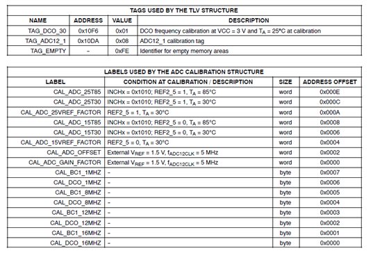
    AFAIK the MSP430F2617 provide TLV information. According to the datasheet it is placed in the Segment A ( 0x10C2 to 0x10FF). Concretely, I want to extract the information of CAL_ADC_15T85 and CAL_ADC_15T30. The first thing that came to my mind was to directly read it from the memory using the IAR memory window while using the FET debugger. Here is the content I got:

    TAG_ADC12_1 starts at the addres 0x10DA.  CAL_ADC_15T85 has and offset addres of 0x0008 and CAL_ADC_15T30 --> 0x0006. 

    So CAL_ADC_15T85 addres would be 0x10E2 and CAL_ADC_15T30 addres 0x10E0. And it's here where I get lost.

    CAL_ADC_15T85 = 0x9D0B ?

    CAL_ADC_15T30 = 0x277F  ?


    I don't know how to apply this values (if they are right) to my formula, if they are represented little or big indian. I guess, because it is and offset, that they could be maybe represented in 2´s arithmetic.

    My °C conversion, formula is    °C = [ (ADC value - 2692) * 1,5] / 15 ; assuming some error due to round off.  (Vref=1,5 V ; Vsensor=0,986V ; TCsensor = 3,55 mV/°C ; from the datasheet).

    I know that the offset temperature value should be applied to the 2692 factor, but all options I tried of values extracted from this memory segment did not help so much or they got even worst results.

    I also add some relevant TLV info extracted from the datasheet, just in case it is needed.

  • Did you ever get an answer to this?

    I am also trying to use the temperature calibration constants for the msp430g2553.

    The datasheet says it has them.

    but the msp430g2553.h header file does not have the definitions of any of the CAL_ADC_xxxxx variables.

    If I add them myself:

    SFR_16BIT( CAL_ADC_15T30 );

    SFR_16BIT( CAL_ADC_15T85 );

    I get them as undefined variables when I link, so the special linker file that patches these addresses up is also missing them.

    Once I get them, how are they to be used? What are the units? In other words, do you add or subtract them from the raw sensor reading, or are they voltages or something else that needs to be converted before being used?

  • Lindsay Even said:
    but the msp430g2553.h header file does not have the definitions of any of the CAL_ADC_xxxxx variables.

    The older G-series devices didn't have them, so maybe someone forgot to add them to the header and linker files.

    However, there is a workaround. Since oyu know the position, you can add them yourself:

    #define CAL_ADC_15T30 (*((unsigned int *) (0x10da+2+0x08)))
    (see below for the +2 and how to use them)

    Marc Ferrer said:
    TAG_ADC12_1 starts at the addres 0x10DA.  CAL_ADC_15T85 has and offset addres of 0x0008 and CAL_ADC_15T30 --> 0x0006. 

    Well, tiuny mistake. The TAG is at 0x10da. The table that belongs ot the tag, however, starts behind the tag at 0x10dc. So your marked values are off by 2 :)

    The values are little-endian values and represent actual ADC readings. So when the sensor is exposed to 30°C, the ADC will return a reading of 0x0b9d with the 1.5V reference. On 85°C, the reading is 0x0dce.
    So the difference between 30°C and 85°C is 0x0dce-0x0b9d = 561 ADC counts. or 561/55=10.2 counts per °C.

    If 'x' is your acrual reading, subtract 0xb9d from it, divide the result by 10.2 and add 30 (as you subtracted the 30° value from it initially).
    You may want to multiply the reading and the 30 value with 10, so you can divide by 102, sparing your the overhead of a floating point division. Or multiply by 100, divide by 102 and get 1/10°C resolution while still using an integer.

    The calibraiton values for the temperature already contain the ADC offset and gain factor as well as the reference calibration. They are actual readings taken at the two temperatures.

**Attention** This is a public forum