This thread has been locked.

If you have a related question, please click the "Ask a related question" button in the top right corner. The newly created question will be automatically linked to this question.

MSP430F5342: Current ramps while sleeping. Is my Errata done correctly on P7/8?

Part Number: MSP430F5342

This is ongoing over multiple board revs and designers over the years. It's showtime for a new product, it's one of the last items, so appreciate any help here. Thanks in advance!

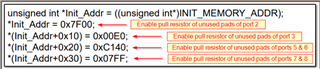
Before getting into the circuits etc, my coder and I have inserted this to address the hidden P7 and P8 pins per errata. Is this correct and sufficient? (Let me know if you need to see the errata and I'll find it, but also looking for general info like if other port settings are also needed below for P7 & P8). 

/* Enable pull resistors of port 7 & 8 pins to save power */
uint16_t * pu16_p78ren_reg = (uint16_t *)0x0266;
*pu16_p78ren_reg = 0x07FF;

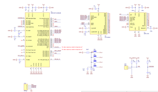
Next, at a high level, the symptoms are that sometimes it will sleep at a nice 27uA. Other times it will go there for a split second, then ramp up to anywhere up to about 1 ma. Almost like a floating port. All unused are output low before sleeping. System uses the internal ADC12, SPI talking to a Motion and RF module (which are not leaking but connected still).  

Additionally, I'm using a low solids flux and tin/lead for prototypes. I seem to be able to get it to stay at 27uA with a good IPA cleaning, soap, you name it I've tried it. Ultrasonic cleaning is not recommended due to the inertial sensor, but that didn't resolve either. This cleaning part seems like the wrong tree, nothing should be that sensitive right? 

Next I've considered ESD damage. So how sensitive are these ports and does a blown port behave this way from static? I have noticed on some I can bring my hand (capacitance) near the chip and it will go back down to 27uA. (I think it's watching me and laughing!). Sounds float related right?

FYI, we have this chip wirelessly updating firmware on sub gig through our own dongle and App, so it's come along way as a Realtime foot controller. But that also means it's complex and we'll need to pick and choose code sections as they relate. I have over 500 of these processors on hand so hope we can make them work. 

  • Hi,

    I found the errata in issue number PORT24 https://www.ti.com/lit/pdf/slaz278

    It says you need to terminate the floating pads for all ports not only the P7 and P8. And it only affect the MSP430F534x devices in 48-pin RGZ package. Maybe this could help you. 

    Best regards,

    Cash Hao

  • Thanks. All (remaining) ports are Outputs set low, some exceptions on SPI or Xtal for example.

    The "FSR" is just a force sensing resistor and those ports are also set to output low when not in use or sleeping. It's resistance is very high at rest. 

    We also use the chip's internal reference to measure battery voltage (CR 2032), maybe that config leaks. Here is the schematic. I have used 470nF in the past for VCORE, doesn't seem to matter.

    My reason for targeting the processor is that I used 1 ohm resistors in place of the coils to isolate the 4 sections of the board power. Motion sensor is also asleep, waking only if shaken and therefor does use some of that 27uA while asleep. The processor has only basics and watching the motion interrupt. Key point, it is capable of doing 27uA sleep total system, but it doesn't if you look at it funny... I think cursing helps some, bathing for sure... flux residue is ultra sensitive so great care is taken to keep boards clean. Is this normal?   

    I will add more info as we go...

    Thanks!

  • Hi,

    The MCU should not be that fragile. I want to check on the Xtal. Could you provide the part number of the X1? And could you test the board without the X1, just using the internal clock source instead. 

    Best regards,

    Cash Hao

  • CH,

    Here's the crystal ECS-.327-7-1210-TR. It only specifies a drive level of 0.1uW - 0.5uW. Made for low power wearables.

    https://ecsxtal.com/store/pdf/ECX-1210.pdf

    I will attempt the no crystal test. Do some crystals leak out of spec like if too hot from solder perhaps? But isn't this just a stone? I would think a cap would be more likely. But keep in mind, this is ongoing with same part #s, different part orders even, and different layouts. Maybe 1/5 will sleep as designed. No silly ideas. 

    Here is that part of the layout if it matters. It's a 2 layer board, no traces under the crystal. I'm using 7pF caps on mine (7 in the part number). 


  • We tested as you suggested, using internal crystal and removed it. No change so not the crystal. We also removed the internal VREF (battery monitor), still the same.

    On my Fluke, this one sleeps for about 200ms at 49uA then starts a ramped curve to about 300uA over approx 5s. Although we're almost certain all unused ports are output low, isn't this what a floating port would look like (imagining)? So I'm back to questioning our implementation of that Port24 errata. Are we missing anything?

    All ideas welcome!

  • FYI, crystal bypass did not work (maybe there's a drive that needs turned off?). However, re-soldering a new one in put it in spec. These statements cannot both be true unless I did it wrong or heating the area did something else as well - will verify. If there is poor solder contact to a crystal, will the processor drive it harder?

    I have a funny feeling I'm about to learn a whole lot more on crystals. 

  • Hi,

     If there is poor solder contact to a crystal, will the processor drive it harder?

    It could cause more current consumption if the soldering is bad for my understanding.

    So I'm back to questioning our implementation of that Port24 errata.

    About this PORT24 errata, have you terminate all the ports before reconfigure those pins to output low?

    Best regards,

    Cash Hao

  • My coder says yes. (I'm a bit shallow on C). I'm trusting he's doing this correctly but noticed only port 7/8 resistors were terminated in his implementation of Port24. (I think). 

    /* Enable pull resistors of port 7 & 8 pins to save power */
    uint16_t * pu16_p78ren_reg = (uint16_t *)0x0266;
    *pu16_p78ren_reg = 0x07FF;

    The remaining ports are set prior to this code above as shown. So yes they are terminated. 

    /* All unused pins of port 1 are digital output pins at 0V with pull resistor enabled to save power */
    u8_unused_pins = BIT0 | BIT2 | BIT4 | BIT5 | BIT6;
    SET_BITS (P1REN, u8_unused_pins);
    CLR_BITS (P1SEL, u8_unused_pins);
    SET_BITS (P1DIR, u8_unused_pins);
    CLR_BITS (P1OUT, u8_unused_pins);

    Is there a difference if the Port24 fix is place before all the other port setup? 

    I'm also confused why the other ports are in this fix as well. My understanding was that only 7/8 are hidden. Are the others just there as example or are there more pins hidden in this package? 

    I think this is why he reduced the above code. I'm only double checking because of the other ports. 

    Here is the full code init showing the sequence.

    static void v_MAIN_Init (void)
    {
        uint8_t u8_unused_pins;
    
        /* Stop watchdog timer to prevent time out */
        WDTCTL = WDTPW + WDTHOLD;
    
        /* Initializes system clock */
        v_MAIN_Configure_Clock ();
    
        /* All unused pins of port 1 are digital output pins at 0V with pull resistor enabled to save power */
        u8_unused_pins = BIT0 | BIT2 | BIT4 | BIT5 | BIT6;
        SET_BITS (P1REN, u8_unused_pins);
        CLR_BITS (P1SEL, u8_unused_pins);
        SET_BITS (P1DIR, u8_unused_pins);
        CLR_BITS (P1OUT, u8_unused_pins);
    
        /* All unused pins of port 2 are digital output pins at 0V with pull resistor enabled to save power */
        u8_unused_pins = BIT0 | BIT1 | BIT2 | BIT3 | BIT4 | BIT5 | BIT6;
        SET_BITS (P2REN, u8_unused_pins);
        CLR_BITS (P2SEL, u8_unused_pins);
        SET_BITS (P2DIR, u8_unused_pins);
        CLR_BITS (P2OUT, u8_unused_pins);
    
        /* All unused pins of port 3 are digital output pins at 0V with pull resistor enabled to save power */
        u8_unused_pins = BIT3 | BIT4 | BIT5 | BIT6 | BIT7;
        SET_BITS (P3REN, u8_unused_pins);
        CLR_BITS (P3SEL, u8_unused_pins);
        SET_BITS (P3DIR, u8_unused_pins);
        CLR_BITS (P3OUT, u8_unused_pins);
    
        /* All unused pins of port 4 are digital output pins at 0V with pull resistor enabled to save power */
        u8_unused_pins = BIT4 | BIT5 | BIT6 | BIT7;
        SET_BITS (P4REN, u8_unused_pins);
        CLR_BITS (P4SEL, u8_unused_pins);
        SET_BITS (P4DIR, u8_unused_pins);
        CLR_BITS (P4OUT, u8_unused_pins);
    
        /* All unused pins of port 5 are digital output pins at 0V with pull resistor enabled to save power */
        u8_unused_pins = BIT0 | BIT1 | BIT2 | BIT6;
        SET_BITS (P5REN, u8_unused_pins);
        CLR_BITS (P5SEL, u8_unused_pins);
        SET_BITS (P5DIR, u8_unused_pins);
        CLR_BITS (P5OUT, u8_unused_pins);
    
        /* All unused pins of port 6 are digital output pins at 0V with pull resistor enabled to save power */
        u8_unused_pins = BIT0 | BIT1 | BIT2 | BIT4 | BIT5 | BIT6 | BIT7;
        SET_BITS (P6REN, u8_unused_pins);
        CLR_BITS (P6SEL, u8_unused_pins);
        SET_BITS (P6DIR, u8_unused_pins);
        CLR_BITS (P6OUT, u8_unused_pins);
    
        /* Enable pull resistors of port 7 & 8 pins to save power */
        uint16_t * pu16_p78ren_reg = (uint16_t *)0x0266;
        *pu16_p78ren_reg = 0x07FF;
    
        /* All unused pins of port J are digital output pins at 0V with pull resistor enabled to save power */
        u8_unused_pins = BIT0 | BIT1 | BIT2 | BIT3 | BIT4 | BIT5 | BIT6 | BIT7;
        SET_BITS (PJREN, u8_unused_pins);
        SET_BITS (PJDIR, u8_unused_pins);
        CLR_BITS (PJOUT, u8_unused_pins);
    

    We are also going to test some simplified code to help isolate. I did have some progress with more heat on that crystal yesterday, so I do think it's the crystal that's hyper sensitive and very tiny pads, I switched to silver/tin solder as well. The lead was also messing with my battery contacts under stress and would break off. 

    Thanks for your help and questions!

    (Not sure I want to ask, but there's a SYS14 that also talks about leakage after a PUC. Same code fix, slight change in the address only. It is extremely vague. I tried it, no change.)

  • Hi,

    It seems promising. If you have further issue, please update it here.  

    We are also going to test some simplified code to help isolate. I did have some progress with more heat on that crystal yesterday, so I do think it's the crystal that's hyper sensitive and very tiny pads, I switched to silver/tin solder as well. The lead was also messing with my battery contacts under stress and would break off. 

    Best regards,

    Cash Hao

  • Thanks, will do.

    So far I have mixed results even with improved soldering: Either 27uA or 120uA 'ish. This is far from the 1ma seen prior, and indicates a strong interaction. The residual leakage is being investigated, and I'll close out after to recognize your input on the crystal. You're very helpful. I just don't understand how something could be so sensitive (like you say).

    One question, my crystal is paired with 7 uF caps which is on the smaller side of the range out there in the world. Would their 12.5uF versions have any effect on power needs? Thinking more cap storage somehow improves energy utilization???

    Thanks! 

  • Also, load cap for the crystal spec is 7pF so my pair of 7pF caps isn't considering parasitic. But it's right next to it. 

    Ya know, maybe I'm just not load matched bc other symptoms include NOT being able to stabilize the crystal and having to use internal at times. I bet this is related.  

  • Hi, sorry to drag this on... we removed the crystal and caps. Not needed actually (best part is no part). 

    However, I still have no control over leakage. I'm sending a unit to my programmer today to look at every port closely. But short of something really stupid, I think there's still an issue here, across several revs of the chip, and several layouts, and by several people. 

    Not sure if I mentioned this, but on some units I can place my hand over the device and the current drops to the expected 27uA. Since I don't have superpowers (yet), is this a symptom of anything else?

  • HI,

    Sorry for the late response. I was on vocation last week. 

    Is it possible to cut off all the connections on our board expect the VCC and GND and measure the current of the MCU itself. It can isolate the hardware influence. 

    Best regards,

    Cash Hao

**Attention** This is a public forum