This thread has been locked.

If you have a related question, please click the "Ask a related question" button in the top right corner. The newly created question will be automatically linked to this question.

MSP430FR2433: ADC stuck at the line

Part Number: MSP430FR2433

Hi,

I have been configuring ADC module on msp430fr2433 for serval days, but  the program just stuck at the specific line at line 35.I can't handle it. Could you check this please?

#include <msp430.h>

/**
 * main.c
 */
int main(void)
{
	WDTCTL = WDTPW | WDTHOLD;	// stop watchdog timer
	

	P1DIR &= ~BIT5;
	P1DIR |= BIT0 + BIT1;
	P1OUT |= BIT0 + BIT1;
	P1OUT &= ~(BIT0 + BIT1);

	PM5CTL0 &= ~LOCKLPM5;


	ADCCTL0 |= ADCON + ADCSHT_2;//采样保持时钟源默认即ADC时钟,ADC时钟源默认MODCLK=5MHz,采样保持16个ADC时钟周期
	ADCCTL1 |= ADCCONSEQ_2;
	ADCMCTL0 |= ADCINCH_13 + ADCSREF_1;//15通道,使用内部1.5V参考电压
	SYSCFG2 |= ADCPCTL5;           //A5口输入
	ADCIE |= ADCIE0;            //使能ADC中断
	PMMCTL2 |= INTREFEN;//使能内部参考电压


	for(;;)
	{
	   __delay_cycles(50);
	   ADCCTL0 |= ADCENC + ADCSC;

	   //ADCIFG |= ADCIFG0;
	 __bis_SR_register(CPUOFF + GIE);
	 __no_operation();
	 if(ADCMEM0 > 512)
	     {
	         P1OUT |= BIT0;
	         __delay_cycles(1000000);
	     }
	     else
	     {
	         P1OUT &= ~BIT0;
	         __delay_cycles(1000000);
	     }
	 }

}


#if defined(__TI_COMPILER_VERSION__) || defined(__IAR_SYSTEMS_ICC__)
#pragma vector=ADC_VECTOR
__interrupt
#elif defined(__GNUC__)
__attribute__((interrupt(ADC_VECTOR)))
#endif
void ADCLED(void)
{

    switch(__even_in_range(ADCIV,12))
    {

        case  0: break; //No interrupt
        case  2: break; //conversion result overflow
        case  4: break; //conversion time overflow
        case  6: break; //ADC10HI
        case  8: break; //ADC10LO
        case 10: break; //ADC10IN
        case 12:        //ADC10IFG0
            __bic_SR_register_on_exit(CPUOFF);
                P1OUT |= BIT1;
                __delay_cycles(1000000);
                P1OUT &= ~BIT1;
                break;
        default:break;
    }
    //ADCIFG &= ~ADCIFG0;
}

Best Regards,

Ben

  • Hi Ben,

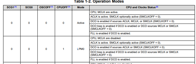
    I find you don't clear ADCIFG bit, and this code should just enter LPM0 mode:

    __bis_SR_register(CPUOFF + GIE);

    Refer this example:

    https://dev.ti.com/tirex/explore/node?node=A__AGc79yyzsPu1J.t4h.Nu.Q__msp430ware__IOGqZri__LATEST

    Thanks!

    Best Regards

    Johnson

  • Hi Johnson,

    I don't clear ADCIFG is because it will reset when the ADCMEM0 get read, and I should have entered LPM0 mode.

    I've seen the example and found I didn't unlock the PMM registers. I should try again.

    Thanks & Regards,

    Ben

  • Hi Johnson,

    I changed my code to below:

    #include <msp430.h>
    
    unsigned int ADC_Result;
    
    /**
     * main.c
     */
    int main(void)
    {
    	WDTCTL = WDTPW | WDTHOLD;	// stop watchdog timer


    	P1DIR |= BIT0 + BIT1;
    	P1OUT |= BIT0 + BIT1;
    	P1OUT &= ~(BIT0 + BIT1);
    
    	SYSCFG2 |= ADCPCTL1;        //A5口输入
    
    	PM5CTL0 &= ~LOCKLPM5;
    
    
    	ADCCTL0 |= ADCON + ADCSHT_2;//采样保持时钟源默认即ADC时钟,ADC时钟源默认MODCLK=5MHz,采样保持16个ADC时钟周期
    	ADCCTL1 |= ADCSHP;
    	ADCMCTL0 |= ADCINCH_5 + ADCSREF_1;//15通道,使用内部1.5V参考电压
    
    	ADCIE |= ADCIE0;            //使能ADC中断
    
    	PMMCTL0_H = PMMPW_H;
    	PMMCTL2 |= INTREFEN;//使能内部参考电压
        __delay_cycles(400);


    	while(1)
    	{
    
    	   ADCCTL0 |= ADCENC + ADCSC;
    
    	   //ADCIFG |= ADCIFG0;
    	 __bis_SR_register(CPUOFF + GIE);
    	 __no_operation();
    	 if(ADC_Result > 512)
    	     {
    	         P1OUT |= BIT0;
    	         //__delay_cycles(1000000);
    	     }
    	     else
    	     {
    	         P1OUT &= ~BIT0;
    	         //__delay_cycles(1000000);
    	     }
    	 }
    
    }
    
    
    #if defined(__TI_COMPILER_VERSION__) || defined(__IAR_SYSTEMS_ICC__)
    #pragma vector=ADC_VECTOR
    __interrupt
    #elif defined(__GNUC__)
    __attribute__((interrupt(ADC_VECTOR)))
    #endif
    void ADCLED(void)
    {
    
        switch(__even_in_range(ADCIV,12))
        {
    
            case  0: break; //No interrupt
            case  2: break; //conversion result overflow
            case  4: break; //conversion time overflow
            case  6: break; //ADC10HI
            case  8: break; //ADC10LO
            case 10: break; //ADC10IN
            case 12:        //ADC10IFG0
                __bic_SR_register_on_exit(CPUOFF);
                ADC_Result = ADCMEM0;
                    break;
            default:break;
        }
        //ADCIFG &= ~ADCIFG0;
    }
    

    but it will stuck at line 41 after 2or3 cycles in the debug. I don't know what‘s going on.

    Best Regards,

    Ben

  • > ADCCTL0 |= ADCENC + ADCSC;

    > __bis_SR_register(CPUOFF + GIE);

    If you're stepping with the debugger, it is highly probable that the ADC will complete between these two lines, and the ISR wakeup will be lost. Even if you're not stepping, there's some possibility of this race happening, since the timing is very close.

    Try inserting this before the first line (i.e. before setting ADCSC):

    >  __disable_interrupt(); // Close window to avoid race

  • Hi Ben,

    I agree with Bruce, you can try this method:

    Code: 

    __disable_interrupt();

    ADCCTL0 |= ADCENC + ADCSC;

    __bis_SR_register(CPUOFF + GIE);

    Thanks!

    Best Regards

    Johnson

  • Hi Johnson,

    Thank you Bruce and Johnson. I tried your code and it runs well. But now comes up a problem that the ADCMEM0 can be read out a number other than 0 without an analog input. I'm really confused.

    Best Regards,

    Ben

  • Hi Ben,

    If you don't connect any analog input, this pin keep floating, thus we have value.

    You can try to connect this pin to ground, then the value will keep around 0.

    Thanks!

    Best Regards

    Johnson

  • >SYSCFG2 |= ADCPCTL1; //A5口输入

    >ADCMCTL0 |= ADCINCH_5 + ADCSREF_1;//15通道,使用内部1.5V参考电压

    Which ADC input are you using? If you want A1 (P1.1) use ADCINCH_1. If you want A5 (P1.5) use ADCPCTL5 [Ref data sheet (SLASE59D) Table 6-17].

    If you're using the Launchpad, P1.1 is jumpered to LED2, and P1.5 (A5) is jumpered to the backchannel UART, so P1.6 (A6: ADCPCTL6/ADCINCH_6) might be  a better choice.

  • If you want A1 (P1.1) use ADCINCH_1. If you want A5 (P1.5) use ADCPCTL5 [Ref data sheet (SLASE59D) Table 6-17].

    Do you mean the input pin and the ADCINCH should be matched?

  • Hi Ben,

    If you use lanuchpad, there are some other circuit, like LED, UART....

    Thus in order to use a ADC channel without any other connection, the P1.6 is a good choice.

    Thanks!

    Best Regards

    Johnson

  • Yes, the "5" in each of ADCPCTL5 and ADCINCH_5 both refer to pin A5.

**Attention** This is a public forum