This thread has been locked.

If you have a related question, please click the "Ask a related question" button in the top right corner. The newly created question will be automatically linked to this question.

MSP430FR2153: Activate XT1 when it is not used for any function inside the system

Part Number: MSP430FR2153

Hi experts,

My customer is building a product using MSP430FR2153.

They are considering using XT1 in the following ways.
1. Activate the XT1 clock immediately after power-on (start oscillation)
2. Use REFO as the source of ACLK, MCLK, and SCLK until XT1 clock oscillation stabilizes.
3. When the outgoing XT1 clock is stable, switch the ACLK, MCLK, and SCLK sources to XT1.

Could you please tell me about the following question here.

Q1: Am I correct in understanding that XT1 can be enabled in Active Mode, LPM0~4 by clearing XT1AUTOOFF?

Q2: In other words, Am I correct in understanding that clearing XT1AUTOOFF will start XT1 oscillation even if it is not being used for any internal system function?

Q3: Is there a register to check whether XT1 is currently oscillating (in other words, active)?

Q4: If 1 is not set after clearing OFIFG (pass line 88 of the code below), does it mean that XT1 is definitely stable?
They have added a 1.5sec wait in the program to wait for XT1 to stabilize oscillation. The reason is that it takes 80ms to exit line 88 of the code below, whereas it takes about 1.2s for the oscilloscope to stabilize the oscillation.

#include <msp430.h>

int main(void)
{
    WDTCTL = WDTPW | WDTHOLD;               // Stop watchdog timer

    CSCTL3 |= SELREF__REFOCLK;               // Set REFO as FLL reference source
    CSCTL4 |= SELA__REFOCLK;  // Set ACLK = REFO = 32768Hz
    CSCTL7 &= ~(XT1AUTOOFF);      // Clear XT1 and DCO fault flag

    P2SEL1 |= BIT6 | BIT7;                  // P2.6~P2.7: crystal pins
    do
    {
        CSCTL7 &= ~(XT1OFFG | DCOFFG);      // Clear XT1 and DCO fault flag
        SFRIFG1 &= ~OFIFG;
    } while (SFRIFG1 & OFIFG);              // Test oscillator fault flag

    // Port Configuration all un-used pins to output low
     P1OUT = 0x00; P2OUT = 0x00;
     P3OUT = 0x00; P4OUT = 0x00;
     P5OUT = 0x00; P6OUT = 0x00;
     P1DIR = 0xff; P2DIR = 0xff;
     P3DIR = 0xff; P4DIR = 0xff;
     P5DIR = 0xff; P6DIR = 0xff;

    PM5CTL0 &= ~LOCKLPM5;                   // Disable the GPIO power-on default high-impedance mode
                                            // to activate previously configured port settings
    while(1)
    {
//        P1OUT ^= BIT0;                      // Toggle P1.2 using exclusive-OR
        __delay_cycles(1000000);           // Delay for 10000000*(1/MCLK)=1.25s
    }
}

The basic software is complete and development is nearing its climax. I am sorry, but I would appreciate an answer by 11/15.

Best regards,
O.H

  • Hi O.H, 

    I think page 103 in the User's Guide answers most of your questions:

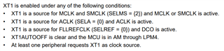
    Q1 and Q2: Yes, this is correct. That is one of the conditions that will enable XT1 as described here:

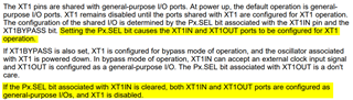
    Q3: From Section 3.2.4 of the User's Guide--you can check the Px.SEL bit associated with the XT1IN port. It should be set if XT1 is active.

    Q4: I am only seeing 33 lines of code in the snippet you have provided here. Is there more to the code so I can take a look at line 88?

    Best,
    Amruta

  • Hello Amruta,

    Thank you for your quick reply.

    I understood about Q1, Q2.

    Q3: From Section 3.2.4 of the User's Guide--you can check the Px.SEL bit associated with the XT1IN port. It should be set if XT1 is active.

    By the way, if the CPU is in Active Mode and XT1AUTOOFF=1, is there any register or method to determine if XT1 is active/non-active?
    In the above case, I think that active/non-active cannot be determined by the Px.SEL bit, but only by the REF bits such as MCLK, SMCLK, ALCK, CLK, PLL, WDT, etc. that XT1 is not set.

    Q4: I am only seeing 33 lines of code in the snippet you have provided here. Is there more to the code so I can take a look at line 88?

    Sorry. I was leaving out unnecessary code. The time to exit lines 8~12 is 80ms.

    Best regards,
    O.H

  • Hi,

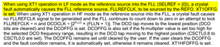
    For Q3: Take a look at this screenshot from Section 3.2.13 of the user guide:

    Since it looks like you are using XT1 in LF mode, if a crystal fault occurs, XT1OFFG is set. You can check this bit to see if XT1 is active or not.

    For Q4: I am still not sure I understand your question--Table 5-3 or Table 5-4 of the datasheet describes the start up times for the crystal oscillator. Are you saying that they have set 1.5 s of a delay to wait for the oscillation to stabilize because it is currently taking 1.2 seconds to stabilize? I am not sure how the program execution time of 80 ms relates to your question. Are you asking if there is a way to check when XT1 is stable?

    Best,
    Amruta 

  • Hi Amruta,

    Thank you for the reply.

    I understood about Q3.

    Are you saying that they have set 1.5 s of a delay to wait for the oscillation to stabilize because it is currently taking 1.2 seconds to stabilize? I am not sure how the program execution time of 80 ms relates to your question. Are you asking if there is a way to check when XT1 is stable?

    Yes, as described above.

    To elaborate on the background, the customer wants to minimize as much time as possible for XT1 to stabilize after the device is reset and powered on.
    Currently the microcontroller is reset as a countermeasure for electrostatic testing.
    They needs to receive UART data immediately after reset.
    The baud rate is 4800, so they are using a 38.4 kHz crystal with a low error rate.
    They use REFO to receive data until the crystal stabilizes, but the error rate is high.
    They actually miss data and they are in a situation where they want to be able to use XT1 as soon as possible.
    They are putting in a 1.5s delay to give us some leeway, but they would like to find a way to make sure it is stable in a shorter time.

    Best regards,
    O.H

  • Hi,

    XT1 does take time to stabilize. When the power switches off are they in LPM mode?

  • Hi Amruta,

    So am I correct in understanding that putting a 1.5s delay is a safe measure?
    (The way to monitor OFIFG with do~while() is to determine from the actual operating conditions.)

    It should not go into the LPM mode.

    Best regards,
    O.H

  • Yes, it is. You can possibly reduce this time, as you had mentioned it only took 1.2 seconds to stabilize on the oscilloscope, but you will need at least 1000 ms. 

**Attention** This is a public forum